PNEUMATIC CONTROL FUNDAMENTALS
89
ENGINEERING MANUAL OF AUTOMATIC CONTROL
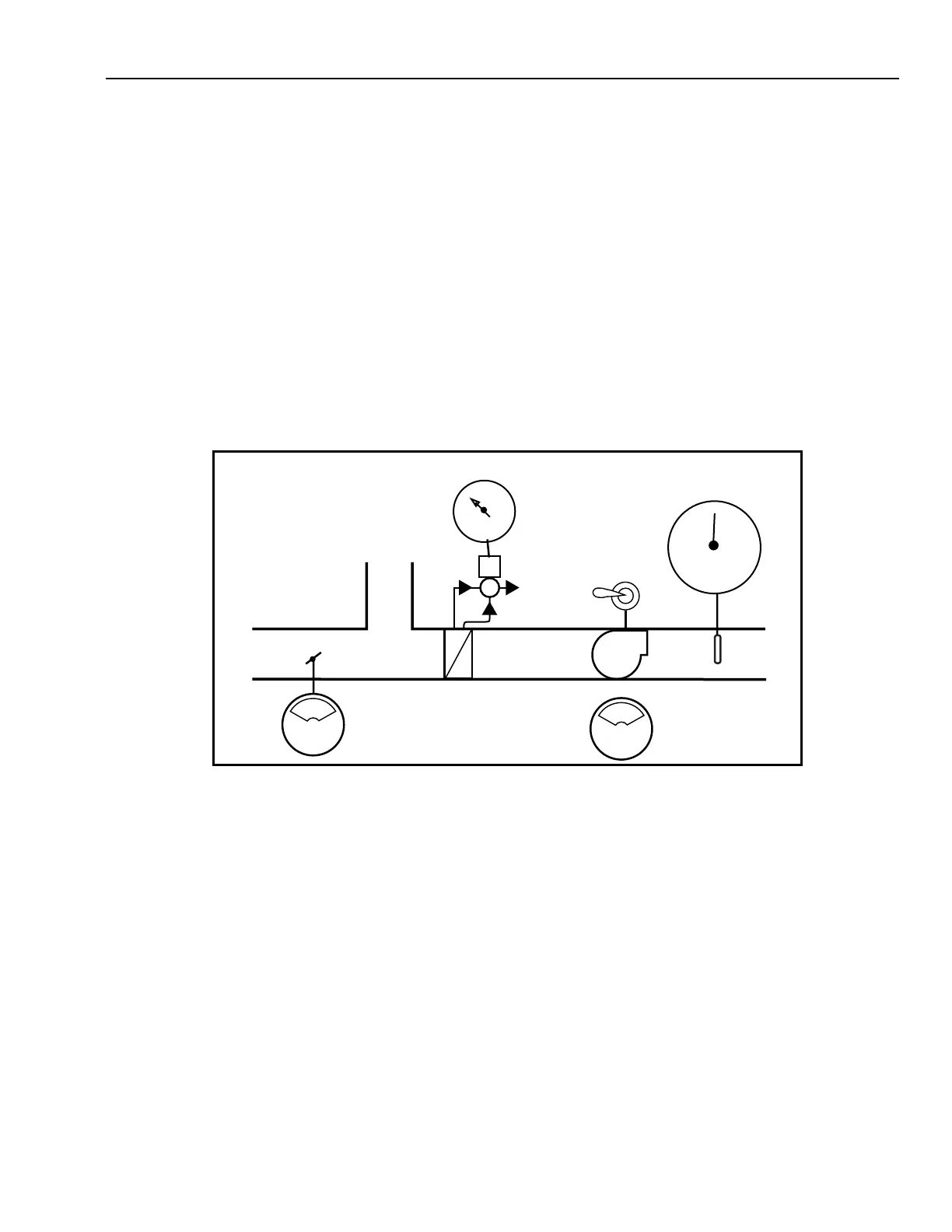
The Discharge Air Temperature Indicator is fed from the
pneumatic discharge air temperature sensor and the Three-Way
Va lve Gauge is fed from the valve control line.
When pneumatic automation panels are located local to the
HVAC system, they are usually connected with 1/4 inch plastic
tubing. When there are many lines at extended lengths, smaller
diameter plastic tubing may be preferable to save space and
maintain responsiveness. When the panel devices are remote,
the air supply should be sourced remotely to avoid pressure
losses due to long flow lines. The switching air may be from
the automation panel or it may be fed via a remote restrictor
and piped in an exhaust configuration.
0
10
20
30
100
90
80
70
60
50
40
30
20
10
0
PSI
DISCHARGE AIR
TEMPERATURE
O
P
E
N
O
N
RETURN
AIR
SUPPLY
FAN
OUTSIDE
AIR
AHU 6
ON OFF
COOLING
COIL
M10297
4-11 PSI
NORMALLY
OPEN
PNEUMATIC CENTRALIZATION
Building environmental systems may be pneumatically
automated to any degree desired. Figure 73 provides an
example of the front of a pneumatic automation panel. This
panel contains pneumatic controls and may be local to the
controlled HVAC system, or it may be located centrally in a
more convenient location.
In this example, the on-off toggle switch starts and stops the
fan. The toggle switch may be electric, or pneumatic with a
Pneumatic-Electric (P/E) relay.
Two pneumatic “target” gauges are shown for the outside
air damper and the supply fan. The ON/OFF Supply Fan Gauge
is fed from a fan proof-of-flow relay, and the OPEN/CLOSED
Damper Gauge is fed from the damper control line.
Fig. 73. Pneumatic Centralization