ENGINEERING MANULA OF AUTOMATIC CONTROL
INDIVIDUAL ROOM CONTROL APPLICATIONS
418
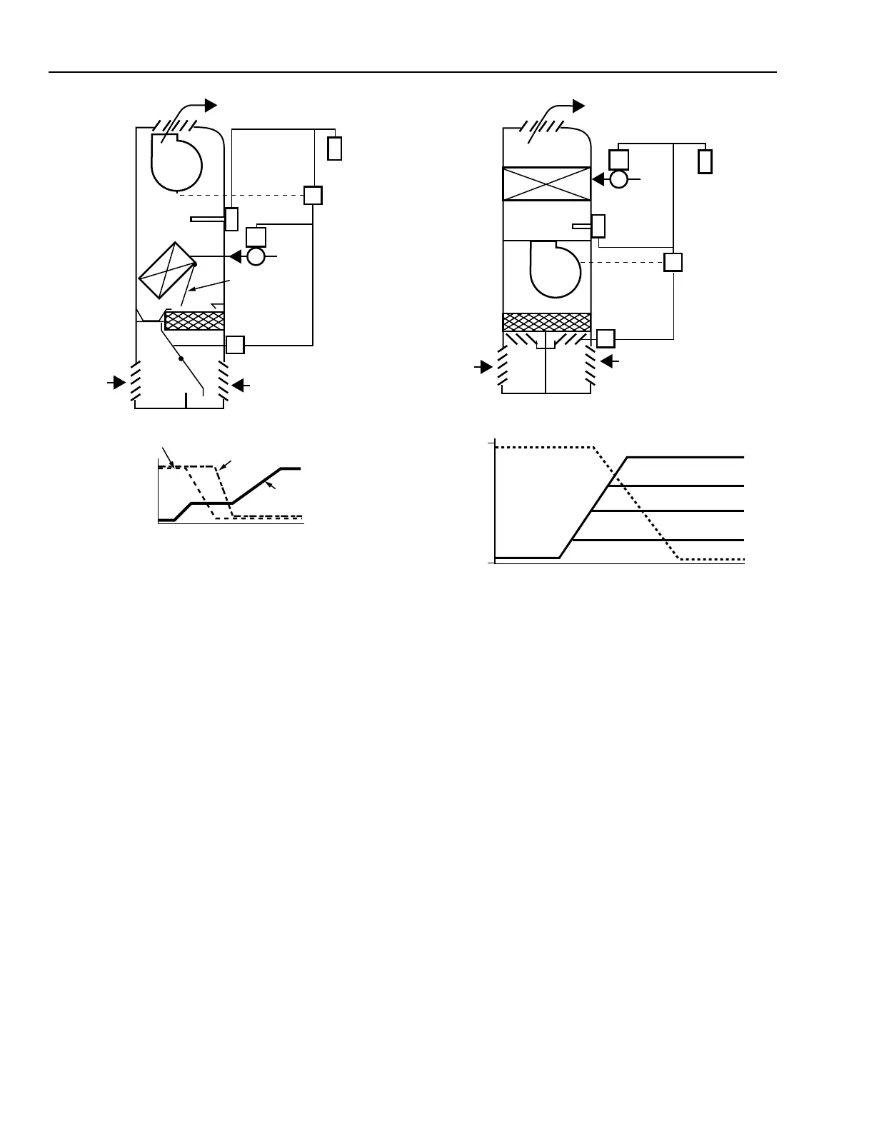
Fig. 25. Unit Ventilator Cycle II
Control (Face and Bypass Model).
CYCLE III–VARIABLE OUTDOOR AIR
Cycle III control (Fig. 26) provides a variable percentage of
outdoor air depending on the outdoor air temperature. This cycle
is basically a reheat cycle where a constant cooling air
temperature (usually 55F) is heated to maintain room
temperature. According to ASHRAE’s definition, there is no
minimum or maximum OA damper position.
When space temperature is below the thermostat setpoint,
the outdoor air damper is closed and the return air damper and
coil valve (or face damper) are full open. As space temperature
rises, the mixed air controller modulates the outdoor and return
air dampers to maintain a mixed air temperature of 55 to 60F.
On a further rise in space temperature, the valve or face damper
modulates toward closed.
Whenever the fan turns off, the fan interlock causes the
outdoor and return air dampers to move to the 100 percent return
air position. The coil valve opens and the unit ventilator
functions as a convector.
Unit ventilators with air conditioning can use any of the
control cycles with a mechanical cooling stage. As space
temperature rises, the room thermostat controls the unit
ventilator cooling capacity through the regulation of the cooling
valve or compressor.
Fig. 26. Unit Ventilator Cycle III Control.
Day/Night Setback Control
Unit ventilators can be operated at lower setpoints during
unoccupied hours to save energy. Two commonly used day/
night systems are individual room day/night control and zone
day/night control. Pneumatic actuation is preferred for unit
ventilator control because it operates smoothly and changes
modes of operation through a simple pressure change.
Individual room day/night control uses a day/night room
thermostat that operates at a higher day temperature setpoint and
a lower night temperature setpoint when responding to a call for
heat. During night operation, the outdoor air damper remains
closed, the return air damper and coil valve remain open, and the
fan cycles to maintain the lowered space temperature.
The room thermostat may provide a manual override that
allows occupants to restore the unit ventilator to daytime
setpoint for after-hours occupancy. Return to daytime operation
is optional with the manual override function depending on the
type of thermostat.
C3034
OPEN
OPERATION CYCLE
HEATING
VALVE
FACE AND
BYPASS
DAMPER
OUTDOOR
AIR
DAMPER
FINAL
CONTROL
ELEMENT
POSITION
CLOSED
LOW
SPACE TEMPERATURE
HIGH
DISCHARGE
AIR
OUTDOOR
AIR
MIXING
DAMPER
RETURN
AIR
FACE AND
BYPASS
DAMPER
FILTER
DRAIN
PA N
HEATING
COIL
FAN
VALVE
FAN
INTERLOCK
LOW-LIMIT
TEMPERATURE
CONTROLLER
THERMOSTAT
DAMPER
ACTUATOR
UNIT
VENTILATOR
C3039
DISCHARGE
AIR
OUTDOOR
AIR
OA, RA
DAMPERS
RETURN
AIR
FILTER
HEATING
COIL VALVE
FAN
FAN
INTERLOCK
MIXED AIR
TEMPERATURE
CONTROLLER
THERMOSTAT
DAMPER
ACTUATOR
OPERATION CYCLE
FINAL
CONTROL
ELEMENT
POSITION
LOW
SPACE TEMPERATURE
HIGH
OPEN
CLOSED
VALVE OR
FACE DAMPER
OUTDOOR
AIR DAMPER
OA AT 50°F
OA AT 30°F
OA AT 20°F
OA AT 0°F