ENGINEERING MANUAL OF AUTOMATIC CONTROL
CHILLER, BOILER, AND DISTRIBUTION SYSTEM CONTROL APPLICATIONS
367
The same equation expressed in MMBtuh (million Btu per
hour) is:
DUAL TEMPERATURE SYSTEMS
Figure 99 shows a typical arrangement where the same pipes
carry hot water for heating or chilled water for cooling to the
same terminal units. These are usually fan coil units.
EXAMPLE:
Given: A 100 ton chiller with a TD
W
of 10F.
gpm = MMBtuh x
2000
TD
W
System Objectives
The chilled water control and distribution system should:
1. Provide the minimum flow of chilled water through the
chiller as specified by the manufacturer.
2. Provide a stable pressure difference across supply and
return mains.
3. Prevent freeze-up in chiller and/or coils exposed to
outdoor air.
4. Control system pumps and bypass valves to prevent short-
cycling of pumps or radical pressure changes across
control valves at the terminal units.
In addition, for systems with two or more chillers operating
at once, the chilled water control and distribution system should:
1. Prevent return water from mixing with chilled water
before leaving the chiller plant.
2. Shut off flow through idle chiller(s).
Control of Terminal Units
The heat transfer characteristic is close to linear for a cooling
coil (Fig. 98) because the air to water temperature difference is
lower than that for hot water coils. This means a valve with
either a linear characteristic or an equal percentage characteristic
plug is satisfactory.
100 Tons x
12,000 Btuh
Ton
= 1.2 MMBtuh
gpm =
1.2 MMBtuh x 2000
10
= 240 gpm
Fig. 98. Typical Heat Transfer Characteristic of
a Cooling Coil Supplied with Chilled Water.
FLOW IN GPM
TOTAL HEAT REMOVED
C2403
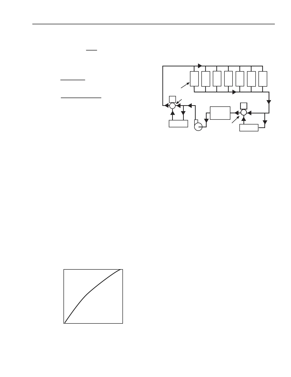
Fig. 99. Two-Pipe Dual-Temperature System.
The three-way valves on the chiller and boiler are used for
changeover. The valve on the chiller is controlled two-position.
The three-way boiler valve is controlled modulating for heating
so that the hot water supply temperature may be reset from the
outside temperature. Boiler minimum flow or temperature may
require system modifications.
Changeover from heating to cooling can be based on outdoor
air temperature, solar gain, outdoor wet-bulb temperature, or a
combination. System bypass or other pressure control method
may also be required for such systems.
Changeover Precautions
A time delay in changing the operation from hot to chilled water
or vice versa is required to avoid putting hot water into the chiller
or chilled water into the boiler. A deadband between heating and
cooling will usually provide enough delay. Hot water to the chiller
can cause the compressor to cut out from high head pressure and/
or damage the compressor. Chilled water to the boiler can cause
thermal shock to the boiler and/or flue gases to condense on the
fireside. Protection for boilers is covered in DUAL BOILER
PLANT CONTROL. For chillers a maximum entering water of
80F is required to avoid excessive refrigerant head (high head
pressure). A thermostatic interlock can provide this safety feature.
MULTIPLE-ZONE DUAL-TEMPERATURE SYSTEMS
Since different zones often have different changeover
requirements, it is often necessary to furnish hot water to one
zone and chilled water to another, as in a curtain wall building
with high solar loads.
BOILER
CHILLER
AIR
SEPARATOR
TERMINAL
UNITS
2-POSITION
3-WAY VALVE
MODULATING
3-WAY VALVE
PUMP
C2920