ENGINEERING MANULA OF AUTOMATIC CONTROL
INDIVIDUAL ROOM CONTROL APPLICATIONS
403
ABBREVIATIONS
The following abbreviations are used:
BMS — Building Management System
ATU —Air Terminal Unit
VAV —Variab le Air Volume
ZEB — Zero Ener gy Band
DDC —Direct Digital Control
CAV — Constant Air Volume
AIR TERMINAL UNIT CONTROL
Air terminal units (ATUs) regulate the quantity and/or
temperature of conditioned air delivered to satisfy the
temperature requirements of a room or space. ATUs are
classified by air handling system design and are available in
many configurations. For information on the air supply to ATUs,
refer to the Air Handling System Control Applications section
and the Building Airflow System Control Applications section.
ATU controls can be as basic as a room sensor controlling a
damper or as complex as a room sensor and an airflow sensor
operating a damper and a reheat coil valve. In all cases, an
individual room control application controls the environment
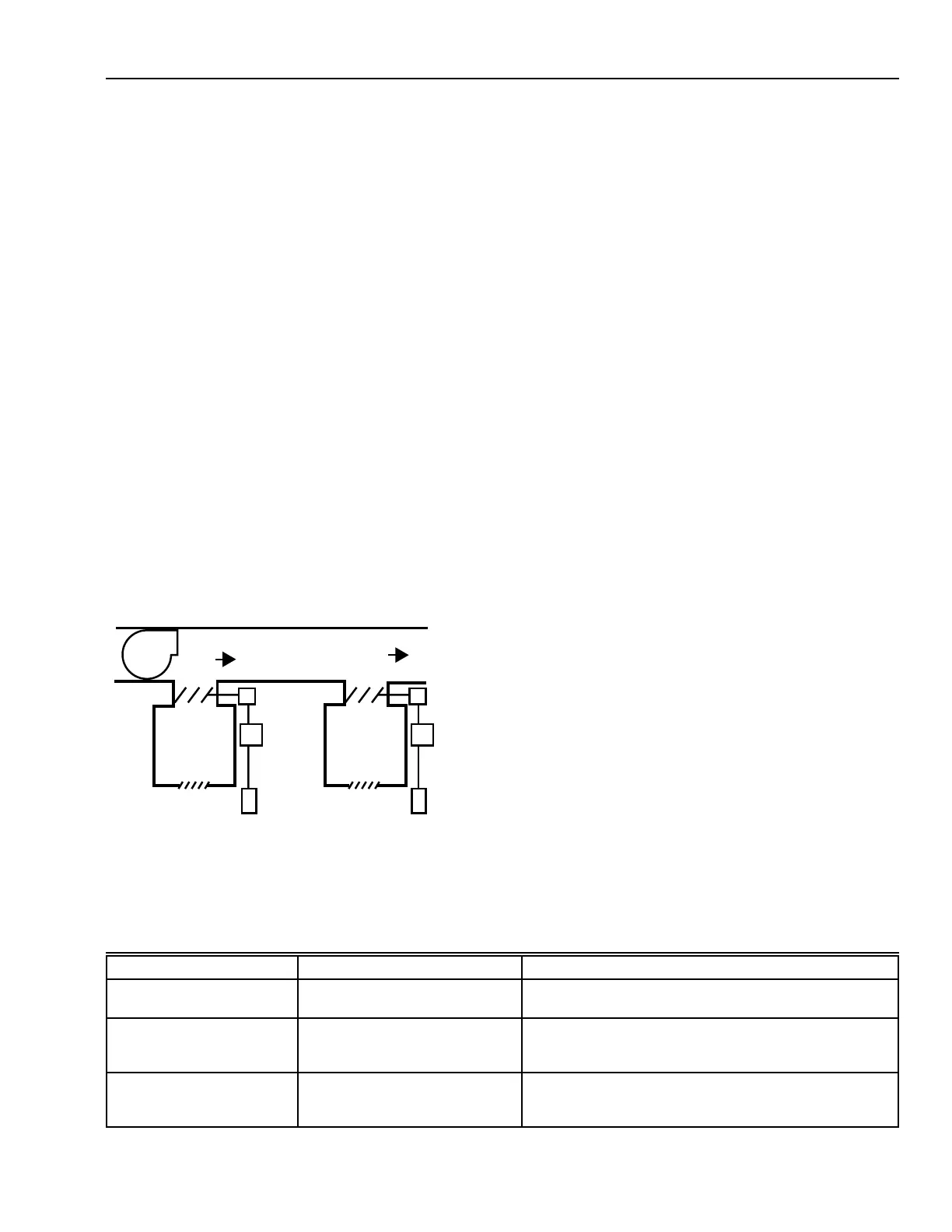
of the room or space. Figure 1 shows basic individual room
control with an ATU.
FAN
ATU
ATU
GRILLE GRILLE
WALL
MODULE
WALL
MODULE
DAMPER
ACTUATOR
TO OTHER
SPACES
CONDITIONED
AIR
CONTROLLER
CONTROLLER
C2399-1
SPACE 2SPACE 1
Fig. 1. Basic Individual Room Control.
VARIABLE AIR VOLUME ATU
A variable air volume (VAV) ATU controls the cooling of a
space by varying the amount of conditioned air supplied rather
than changing the temperature of the conditioned air. Most VAV
systems provide energy savings by reducing the load on the
central fan when cooling loads are less than design and avoid
reheating cooled air.
A system designed to reduce overall system airflow as ATUs
shut down offers the greatest energy savings because system
fans and fan motors operate at lighter loads. These paragraphs
describe the operation of VAV ATUs in single-duct and dual-
duct air handling systems.
PRESSURE-DEPENDENT AND PRESSURE-
INDEPENDENT ATU
A Pressure-dependent ATU is affected by changing duct static
pressures. It may have mechanical minimum and maximum
airflow limits.
A pressure-independent ATU automatically adjusts to duct
static pressure changes because it contains airflow sensors and
controllers to compensate for pressure changes. When used with
DDC systems, the pressure-independent ATU may be
programmed to change the airflow delivered based on the
operating mode. Table 1 describes some modes with the
associated command and comments on the reasoning.
Table 1. AHU Operating Modes and Associated ATU Airflow Settings.
Mode Command Comments
Smoke Purge Mode All associated boxes to 82%
maximum airflow.
AHU was sized with diversity such that the total box
maximum airflows exceed the fan design airflow.
Thermal or IAQ Pre-Purge All the boxes to 50% maximum
airflow.
Take advantage of the fan horsepower cube root
relationship to airflow (fan runs twice as long at one
eighth the horsepower).
Preoccupancy Cool Down Perimeter boxes to 50%
maximum airflow and the interior
boxes to 80% maximum airflow.
Reduce the fan energy per cubic foot of air delivered by
half, match the fan-to-chiller load for better chiller
efficiency and for better dehumidification.