ENGINEERING MANUAL OF AUTOMATIC CONTROL
CONTROL FUNDAMENTALS
15
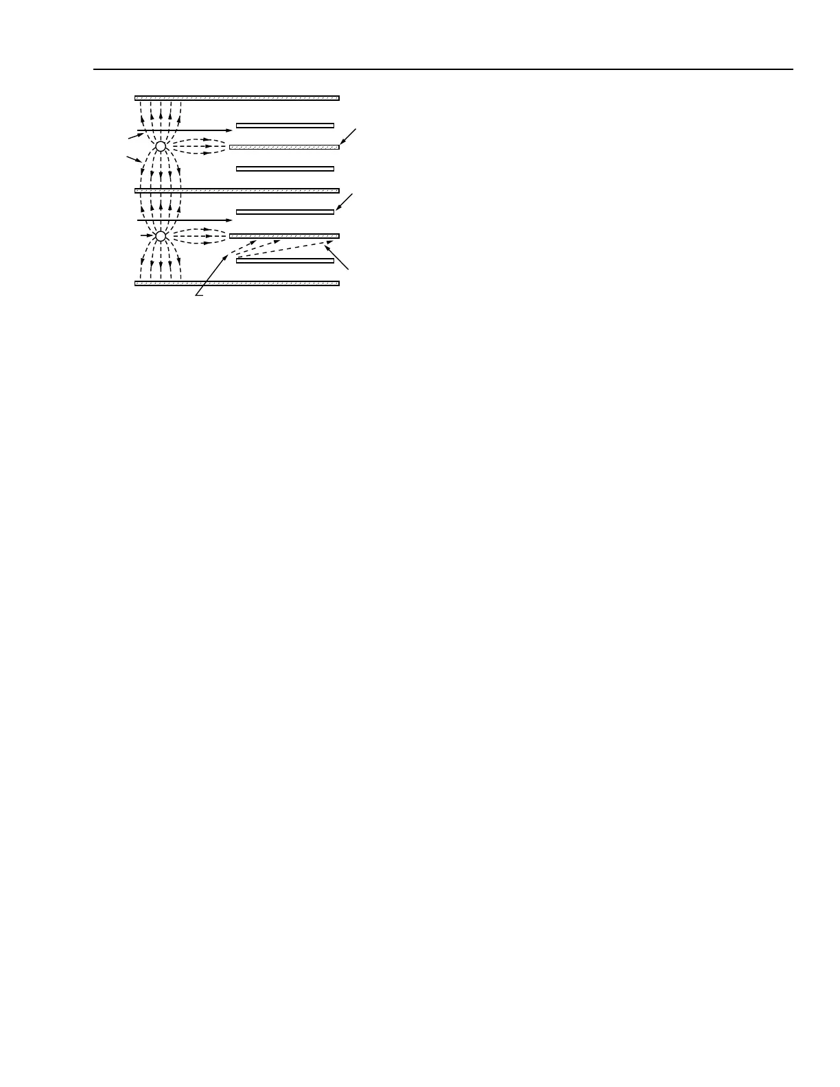
Fig. 18. Electrostatic Filter.
The sensor can be separate from or part of the controller
and is located in the controlled medium. The sensor measures
the value of the controlled variable and sends the resulting
signal to the controller. The controller receives the sensor
signal, compares it to the desired value, or setpoint, and
generates a correction signal to direct the operation of the
controlled device. The controlled device varies the control
agent to regulate the output of the control equipment that
produces the desired condition.
HVAC applications use two types of control loops: open
and closed. An open-loop system assumes a fixed relationship
between a controlled condition and an external condition. An
example of open-loop control would be the control of perimeter
radiation heating based on an input from an outdoor air
temperature sensor. A circulating pump and boiler are energized
when an outdoor air temperature drops to a specified setting,
and the water temperature or flow is proportionally controlled
as a function of the outdoor temperature. An open-loop system
does not take into account changing space conditions from
internal heat gains, infiltration/exfiltration, solar gain, or other
changing variables in the building. Open-loop control alone
does not provide close control and may result in underheating
or overheating. For this reason, open-loop systems are not
common in residential or commercial applications.
A closed-loop system relies on measurement of the
controlled variable to vary the controller output. Figure 19
shows a block diagram of a closed-loop system. An example
of closed-loop control would be the temperature of discharge
air in a duct determining the flow of hot water to the heating
coils to maintain the discharge temperature at a controller
setpoint.
AIRFLOW
AIRFLOW
ALTERNATE
PLATES
GROUNDED
INTERMEDIATE
PLATES
CHARGED
TO HIGH
POSITIVE
POTENTIAL
THEORETICAL
PATHS OF
CHARGES DUST
PARTICLES
POSITIVELY CHARGED
PA RTICLES
SOURCE: 1996 ASHRAE SYSTEMS AND EQUIPMENT HANDBOOK
PATH
OF
IONS
WIRES
AT HIGH
POSITIVE
POTENTIAL
C2714
–
+
–
–
–
–
+
+
+
CONTROL SYSTEM CHARACTERISTICS
Automatic controls are used wherever a variable condition
must be controlled. In HVAC systems, the most commonly
controlled conditions are pressure, temperature, humidity, and
rate of flow. Applications of automatic control systems range
from simple residential temperature regulation to precision
control of industrial processes.
CONTROLLED VARIABLES
Automatic control requires a system in which a controllable
variable exists. An automatic control system controls the
variable by manipulating a second variable. The second
variable, called the manipulated variable, causes the necessary
changes in the controlled variable.
In a room heated by air moving through a hot water coil, for
example, the thermostat measures the temperature (controlled
variable) of the room air (controlled medium) at a specified
location. As the room cools, the thermostat operates a valve
that regulates the flow (manipulated variable) of hot water
(control agent) through the coil. In this way, the coil furnishes
heat to warm the room air.
CONTROL LOOP
In an air conditioning system, the controlled variable is
maintained by varying the output of the mechanical equipment
by means of an automatic control loop. A control loop consists
of an input sensing element, such as a temperature sensor; a
controller that processes the input signal and produces an output
signal; and a final control element, such as a valve, that operates
according to the output signal.