ENGINEERING CMANUAL OF AUTOMATION CONTROL
AIR HANDLING SYSTEM CONTROL APPLICATIONS
225
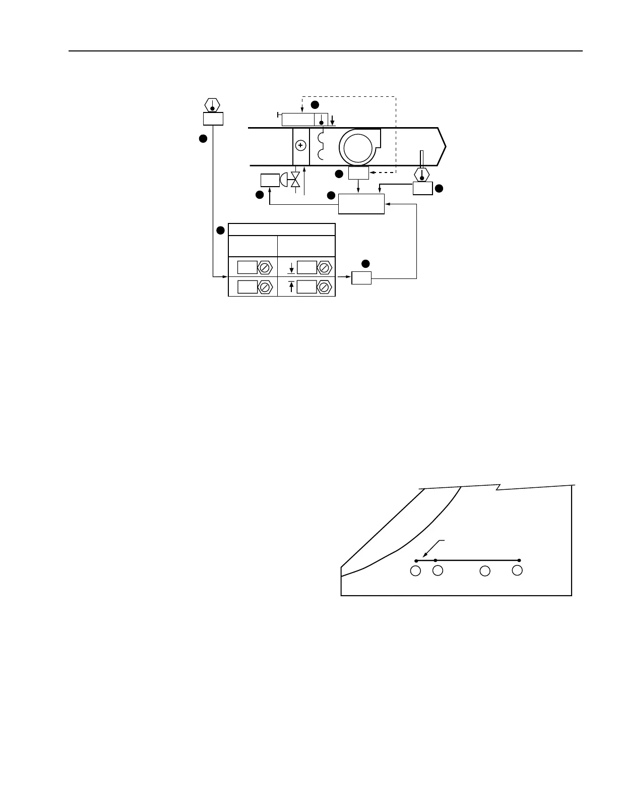
OUTDOOR AIR TEMPERATURE RESET OF SUPPLY AIR TEMPERATURE
Functional Description
M10460
8
CONTROL
PROGRAM
SA
OA
MA
ON
1
3
2
6
4
75
60
74
NORMAL
100
60
RESET SCHEDULE
SETPOINT
OUTDOOR
AIR
SUPPLY AIR
SETPOINT
60
5
7
5
00
Item
No. Function
1,2 Control system energizes when fan is turned on
(See FAN SYSTEM START-STOP CONTROL).
3,4 SA temperature setpoint, as adjusted by reset
schedule, maintained by modulating hot water
valve.
5,6 OA temperature resets the SA temperature setpoint
according to a reset schedule.
7 Hot water valve modulates flow, opens upon loss
of motive force, and closes upon fan shutdown.
8 Control program coordinates SA temperature,
valve, and fan interlock control.
FEATURES
The SA temperature rises as the OA temperature falls
according to a predetermined reset schedule.
CONDITIONS FOR SUCCESSFUL OPERATION
Use multiple inline coil arrangement should be used if a high
temperature rise is required.
SPECIFICATIONS
See FAN SYSTEM START-STOP CONTROL.
Anytime the supply fan runs, heating control shall be enabled.
A SA PID control loop shall modulate the hot water valve to
maintain the SA temperature setpoint. The SA temperature
setpoint shall be reset from 60°F to 100°F as the OA temperature
varies from 60°F to 5°F.
PSYCHROMETRIC ASPECTS
The SA condition depends on the entering air condition and
the temperature rise needed to satisfy the space heating
requirements.
In the following chart it is assumed that:
1. The MA system is set to maintain 60°F DB MA
temperature.
2. The OA temperature reset controller increases the setpoint
of the discharge PID control loop linearly from 60°F to
100°F DB as OA temperature falls from 60°F to 5°F DB.
The following results are obtained:
Item
No. Explanation
1 MA temperature.
2 SA at the beginning of the reset schedule.
3 SA heated to 100°F at outdoor design
temperature.
4 Between 0°F and 60°F OA temperature, SA
temperatures are between points 2 and 3.