ENGINEERING CMANUAL OF AUTOMATION CONTROL
AIR HANDLING SYSTEM CONTROL APPLICATIONS
244
C2562-2
RA 76°F DB,
50% RH
MA
OA 80°F DB,
78°F WB
1
2
3
5
4
COOLING COIL
DISCHARGE
55°F DB
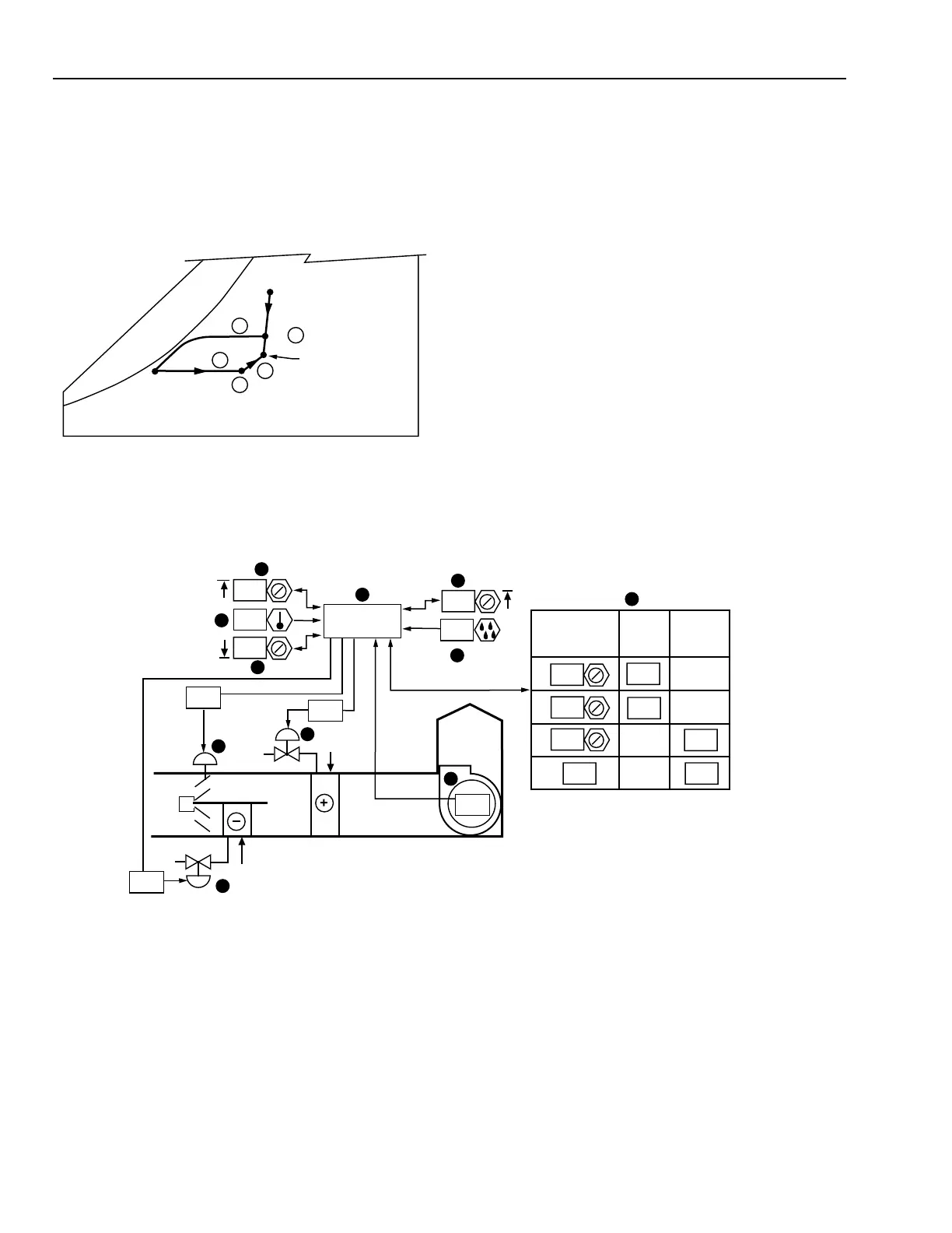
WATER COIL FACE AND BYPASS SYSTEM CONTROL
Functional Description
M10473
SA
11
6
5
2
70
90
32
SUPPLY
FAN
COOL
HEAT
ON
1
CONTROL
PROGRAM
3
4
7
9
76
50
50
72
74
MA
8
10
0
60
10
100
COOL OR
DEHUMIDIFIER
DEMAND
CHW
VALVE
0
100
0
100
FACE
DAMPER
In the following chart it is assumed that:
1. Desired space condition is 76°F DB and a maximum of
50% RH.
2. OA condition is 80°F DB and 78°F WB.
3. Air entering the system is from the ECONOMIZER
CYCLE DECISION application. The system operates on
25 percent OA during the cooling cycle.
4. Cooling coil leaving air temperature is 55°F.
The following results are obtained:
Item
No. Explanation
1Mixed air temperature at cooling design
condition.
2Air entering the cooling coil is cooled along a
line of constant moisture content until
saturation is approached. Near saturation the
moisture content is reduced as the air is
cooled. This process involves both latent and
sensible cooling.
3The final leaving air temperature necessary to
satisfy space requirements will be maintained
by reheating along a constant moisture line.
4 Heating coil discharge.
5 This process line represents the increase in
temperature and humidity that occurs due to
the sensible and latent heat gains in the space.
Item
No. Function
1 Control system energizes when fan is turned
on (See FAN SYSTEM START-STOP
CONTROL).
2-4 Space temperature PI control loops have heat
and cool setpoints with deadband.
5,6 Space humidity sensor and setpoint enable
dehumidification.
7-9 Heating and cooling valves and face and
bypass dampers position for heating, cooling,
and dehumidifying cycles.
10 Stages chilled water and face-and-bypass
damper loading.
11 Control program coordinates cooling, heating,
dehumidifying, and fan and hot water
interlock control.