ENGINEERING CMANUAL OF AUTOMATION CONTROL
AIR HANDLING SYSTEM CONTROL APPLICATIONS
231
The following results are obtained:
Item
No. Explanation
1 Heating of OA occurs along a line of constant
moisture content from 35°F to 70°F.
2 This condition represents the mixing of
preheated air and RA supplied to the system.
C2553-1
RA 75°F DB, 62.5°F WB
PREHEAT AIR
70°F DB
MA
OA 35°F DB, 29°F WB
2
1
MA
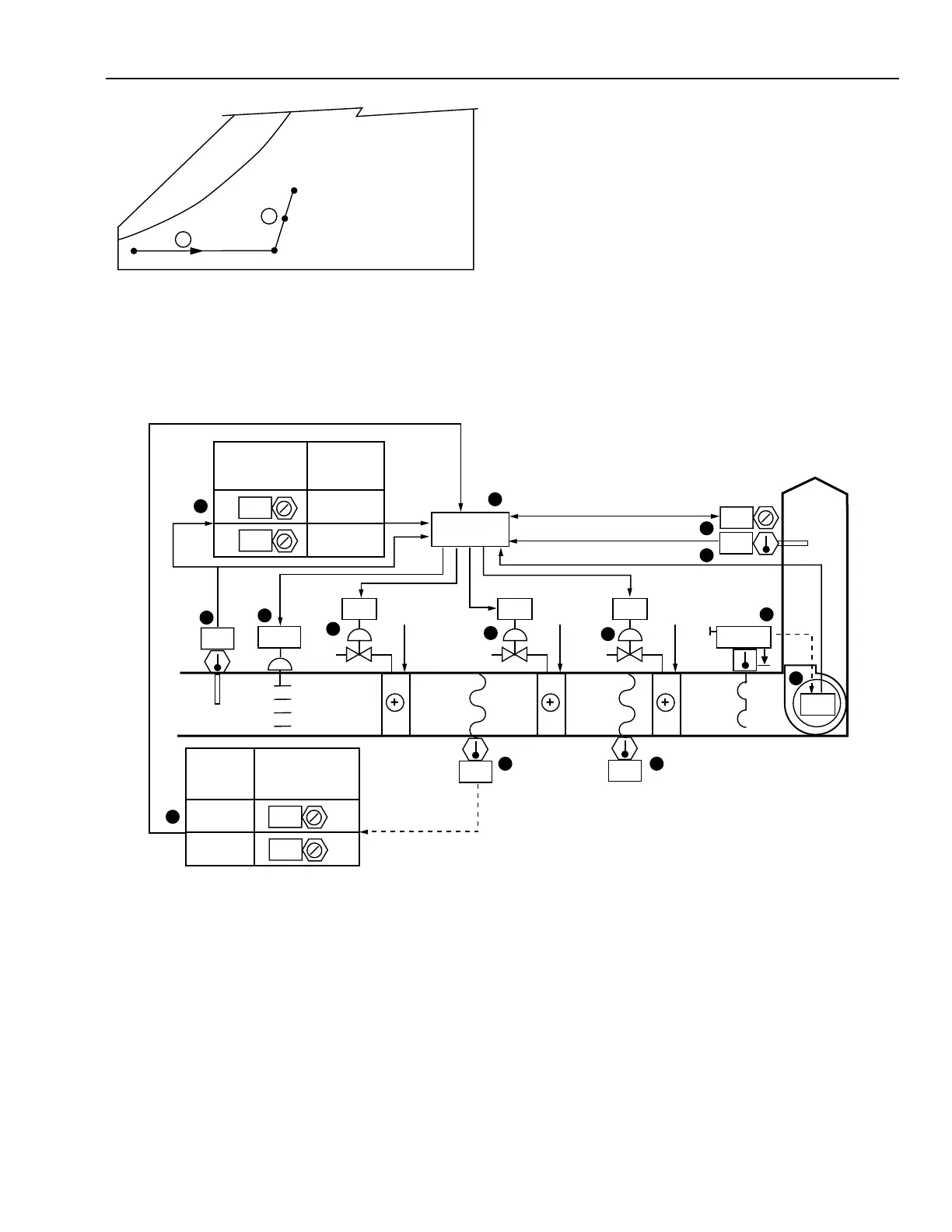
MULTIPLE COIL CONTROL FROM OUTDOOR AND SUPPLY AIR
Functional Description
M10464
5
13
6
CONTROL
PROGRAM
OA
SA
10 14
4
11
2
8
3
7
37
58
N.C.
OPEN NORMAL
COIL
NO. 2
COIL
NO. 1
COIL
NO. 3
11
N.O.
60
N.O.
V1 V2 V3
100
ON
N.O.
64
10
64
1
12
40
35
VALVE 2
PERCENT
OPEN
COIL 1
TEMPERATURE
0
100
9
40
35
OA
TEMPERATURE
VALVE 1
PERCENT
OPEN
0
100
Item
No. Function
1,2 Control system energizes when fan is turned on
(See FAN SYSTEM START-STOP CONTROL).
3OA damper opens when fan runs.
4-6 Supply air PID control loop modulates the coil #3
valve to maintain constant supply temperature.
7-9 Coil #1 is under open loop control by OA
temperature.
10-12 Coil #2 is under open loop control by coil #1
leaving air temperature.
13 Control program coordinates temperature,
ventilation, and fan interlock control.
14 Coil #2 leaving air temperature is for operator
information (unless alarm monitoring is desired).