ENGINEERING MANUAL OF AUTOMATIC CONTROL
SMOKE MANAGEMENT FUNDAMENTALS
177
HVAC
HVAC systems can provide a means for smoke transport
even when the system is shut down (e.g., a bypass damper
venting smoke). Utilizing the HVAC system in smoke control
strategies can offer an economic means of control and even
meet the need for zone pressurization (e.g., pressurizing areas
adjacent to a fire compartment).
CONTROL OF SMOKE
Smoke control uses barriers within the building along with
airflow produced by mechanical fans to contain the smoke. For
some areas, the pressure difference across the barrier can be
used to control the smoke. Where the barriers have large
penetrations, such as door openings, it is easier to design and
measure the control system results by using airflow methods.
Both methods, pressurization and airflow, are discussed in the
following paragraphs.
In addition to life safety requirements, smoke control systems
should be designed to provide a path to exhaust the smoke to
the outdoors, thereby relieving the building of some of the heat
of the fire and the pressure of the gas expansion.
PRESSURIZATION
Pressurization of nonsmoke areas can be used to contain
smoke in a fire or smoke zone. Barriers are required between
the nonsmoke areas and the area(s) containing the smoke and
fire. For the barrier to perform correctly in a smoke control
system, a static pressure difference is required across any
penetrations or cracks to prevent the movement of smoke.
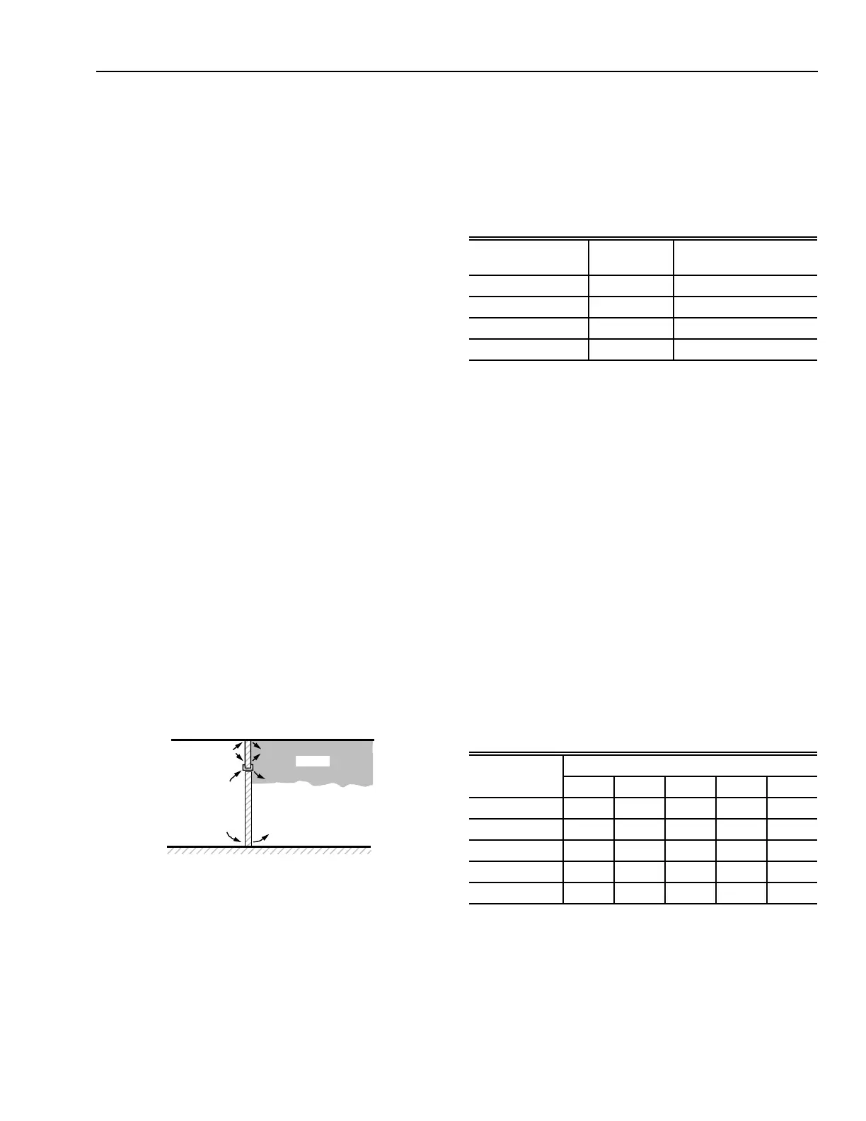
Figure 3 illustrates such an arrangement with a door in a wall.
The high pressure side can act as a refuge or an escape route,
the low pressure side as a containment area. The high pressure
prevents any of the smoke from infiltrating into the high
pressure area.
LOW PRESURE
SIDE
HIGH PRESURE
SIDE
M13023
SMOKE
control system should be able to maintain these minimum
pressure differences while the building is under typical
conditions of stack effect and wind. This table is for gas
temperatures of 1700F adjacent to the barrier. To calculate
pressure differences for gas temperatures other than 1700F, refer
to data in NFPA 92A.
Table 1. Suggested Minimum Design Pressure
Differences Across Smoke Barriers.
Fig. 3. Pressurization Used to Prevent Smoke Infiltration.
Guidelines for pressurization values are found in NFPA 92A,
Recommended Practice for Smoke Control Systems. Table 1
indicates minimum design pressure differences across smoke
barriers. The design pressure difference listed is the pressure
difference between the smoke zone and adjacent spaces while
the affected areas are in the smoke control mode. The smoke
Pressure differences can vary because of fan pulsations, wind,
and doors opening and closing. Short-term variances, from the
suggested minimum design pressure differences in Table 1, do
not seem to have significant effects on the protection furnished
by a smoke control system. There is no actual definitive value
for short-term variances. The value depends on the tightness of
the construction and the doors, the toxicity of the smoke, the
airflow rates, and the volume of the protected space. Occasional
variances of up to 50 percent of the maximum design pressure
difference can be allowed in most cases.
Table 2 lists values for the maximum pressure differences
across doors. These values should not be exceeded so that the
doors can be used when the pressurization system is in
operation. Many door closers require less force when the door
is initially opened than the force required to open the door fully.
The sum of the door closer force and the pressure imposed on
the door by the pressurization system combine only until the
door is opened sufficiently to allow air to move easily through
the door. The force imposed by a door closing device on closing
a door is often different from that imposed on opening a door.
Table 2. Maximum Pressure Difference Across Doors
in in. wc (NFPA 92/92A).
Building Type
Ceiling
Height (ft)
Design Pressure
Difference (in. wc)
Sprinklered Unlimited 0.05
Nonsprinklered 9 0.10
Nonsprinklered 15 0.14
Nonsprinklered 21 0.18
Door Closer
Door Width (in.)
Force (lb ft)
32 36 40 44 48
6 0.45 0.40 0.37 0.34 0.31
8 0.41 0.37 0.34 0.31 0.28
10 0.37 0.34 0.30 0.28 0.26
12 0.34 0.30 0.27 0.25 0.23
14 0.30 0.27 0.24 0.22 0.21
NOTE: Total door opening force is 30 lb ft. Door height
is 7 ft. The distance from the doorknob to the
knob side of the door is 3 in. (ADA has
requirements which conflict with this table.)