ENGINEERING MANUAL OF AUTOMATIC CONTROL
CHILLER, BOILER, AND DISTRIBUTION SYSTEM CONTROL APPLICATIONS
396
Reference Description Reference Description
DDC Controller TI 16 SSF temperature
HEX 1 Heat exchanger TI 18 SRF temperature
QIR 12 Primary flow meter TI 19 PRF temperature
QIR 17 Secondary flow meter TI 32 Heating return temperature
TI 01 Outdoor temperature TIC 21 DHW supply temperature
TI 11 PSF temperature TIC 31 Heating supply temperature
TI 13 PSF temperature Y 14 DHW control valve
TI 15 PRF temperature Y 33 Heating control valve
51219273441 48556370
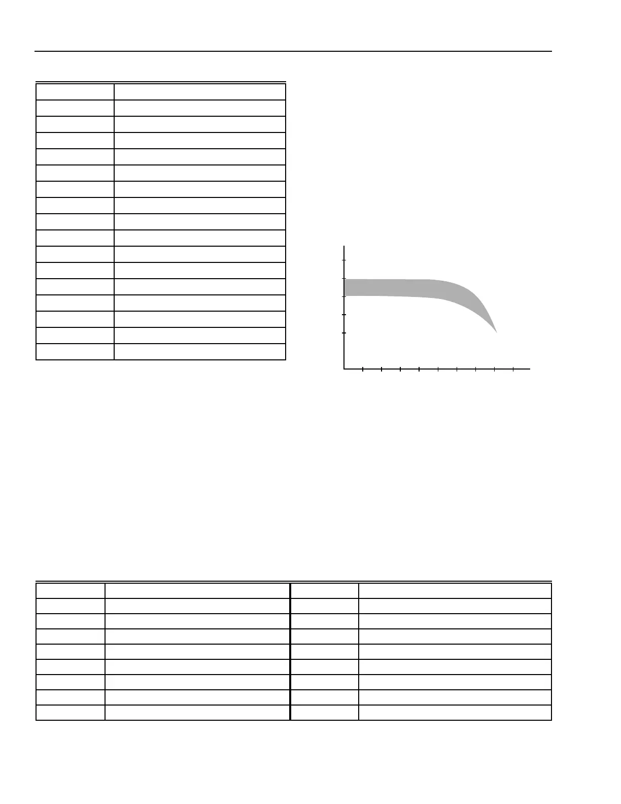
SSF SETPOINT TEMPERATURE (F)
OUTSIDE AIR TEMPERATURE (F) M11442
158
140
122
104
86
ADJUSTABLE RANGE OF
SSF SETPOINT
TEMPERATURE CURVES
HSF = 0.8
HSF = 1.6
Table 13. Description of Figure 142 Controls.
Reference Description
DDC Controller
QIR 02 Cold water metering
QIR 15 Flow meter (heat meter)
TI 01 Outdoor air temperature
TI 11 PSF temperature
TI 14 PRF temperature (heat meter)
TIC 13 PRF temperature
TIC 22 SSF temperature
TIC 31 Loading circuit temperature
TIC 32 HW storage tank temperature
TZA+ 21 High temperature limit (SSF)
Y 12 Control valve primary flow
Y 23 Circulating pump (SSF)
Y 24 Circulating pump (SSF)
Y 33 Circulating pump
Y 34 Charging pump (HW storage tank)
Control Strategies
1. Secondary Supply Flow (SSF) temperature control:
Modulating normally-closed Valve Y 12 in the primary
supply flow (PSF) and TIC 22 control the SSF
temperature. The SSF setpoint is reset based on outdoor
air temperature (Fig. 143). If the primary return flow
(PRF) exceeds the TI 14 temperature limit, the SSF 1
temperature reset schedule is adjusted to a lower
temperature schedule. If the SSF temperature exceeds
the high limit setpoint of hard wired thermostat (TZA+
21), power to valve Y 12 is shut off closing the valve.
2. DHW temperature control: Valve Y 12 in conjunction with
TC 32 maintains the HW storage tank water temperature.
Thermostat TIC 32 supplies the HW storage tank loading
cycle start point. During the loading cycle, SSF water
heats HEX 2, other loads are switched off, and the pumps
Y 24, Y 34 load the HW storage tank. Temperature sensor
TIC 31 turns loading operation off.
3. DHW Circulating pump control: Circulating pump Y 33
is time schedule controlled to maintain the DHW
temperature at the end of the line.
Functional Diagram
Variations of temperatures based on a heat surface factor
(HSF) of radiators in a building (equivalent to a building heat
curve variation) ranging from 0.8 to 1.6 (Fig. 143).
Fig. 143. SSF Temperature Reset Range.
HYBRID BUILDING SUBSTATION
Combination Jet Pump and Heat Exchanger.
The Heating System is mainly used in Eastern Europe or the
CIS and consists of a Hydro-elevator Mixing Valve (jet pump).
Hydro-elevators are mostly uncontrolled devices, mixing the
building return water with supply water according to the hydro-
mechanical configuration in the valve and requires no pump
for heating water circulation in the building heating system
(Fig. 144).
Table 14. Description of Figure 144 Controls.