ENGINEERING MANUAL OF AUTOMATIC CONTROL
CHILLER, BOILER, AND DISTRIBUTION SYSTEM CONTROL APPLICATIONS
352
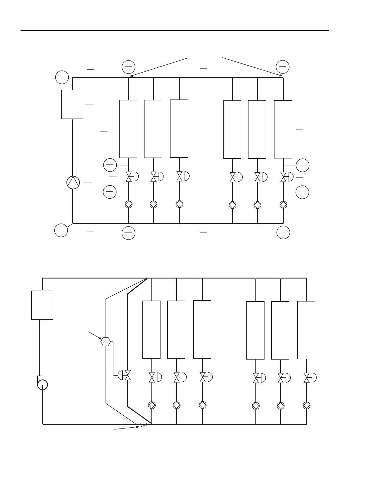
Fig. 74. Single Pump, Pressure Bypass, Direct Return at Full and Half Flow.
Fig. 75. Single Pump, Pressure Bypass System at 90 percent Flow.
26
48.5
RETURN
HEAT/
COOL
COIL
1
V1
B1
HEAT/
COOL
COIL
2
V2
B2
HEAT/
COOL
COIL
3
V3
B3
HEAT/
COOL
COIL
4
V4
B4
HEAT/
COOL
COIL
5
V5
B5
HEAT/
COOL
COIL
6
V6
B6
PUMP
ZERO
REFERENCE
CHILLER
200 GPM
PER
AHU COIL
32
50
36
51
12
3
PD
8
2
PD
4
1
PD
48
54
0
4
1
4
1
PD
12
3
PD
8
44
PD
16
4
24
48
10
2.5
18
46.5
0
0
PD
8
44
PD
10
2.5
6
1.5
PD
6
1.5
PD
6' DROP TOTAL
TOP NUMBERS = FULL FLOW
BOTTOM NUMBERS = HALF FLOW, EACH COIL
PD = PRESSURE DROP
NUMBERS IN CIRCLES = GAUGE PRESSURES
(PUMP INLET = ZERO FOR SIMPLICITY)
8
2
PD
M15061
RETURN
SYSTEM STRAINER
HEAT/
COOL
COIL
1
V1
B1
HEAT/
COOL
COIL
2
V2
B2
HEAT/
COOL
COIL
3
V3
B3
HEAT/
COOL
COIL
4
V4
B4
HEAT/
COOL
COIL
5
V5
B5
HEAT/
COOL
COIL
6
V6
B6
PUMP
1080 GPM
50' HEAD
SUPPLY
3.2' DROP
3.2' DROP
*DP SETPOINT = 34'
CHILLER
9.6' DROP
SYSTEM WITH 90% FLOW THROUGH EACH COIL
180 GPM
PER
AHU COIL
*DIFFERENTIAL PRESSURE CONTROLLER SETPOINT = 50' -9.6' -3.2' -3.2' = 34'
DP
M15062