ENGINEERING CMANUAL OF AUTOMATION CONTROL
AIR HANDLING SYSTEM CONTROL APPLICATIONS
242
CONDITIONS FOR SUCCESSFUL OPERATION
1. All zones are connected to load analyzer program to
satisfy total load requirements. In larger systems only
selected diverse zone loads are connected. Zones that may
be allowed to go out of control (storage rooms, etc.)
should not be connected to the load analyzer program.
2. Each zone duct has a balancing damper following the
mixing dampers to ensure design volume to each zone.
SPECIFICATIONS
See FAN SYSTEM START-STOP CONTROL.
Anytime the supply fan runs, cooling control shall be enabled.
Each zone cold deck mixing damper shall be modulated to
maintain zone space temperature setpoint.
The chilled water valve shall be modulated to maintain the
cold deck temperature setpoint.
Zone mixing dampers shall modulate from 0 to 100% open
to the cold deck as their respective zone demands for cooling
vary from zero to 50%.
The cold deck temperature setpoint shall be reset from the
mixed air temperature to 55°F as the cooling demand from the
zone with the greatest cooling demand varies from 50 to 100%.
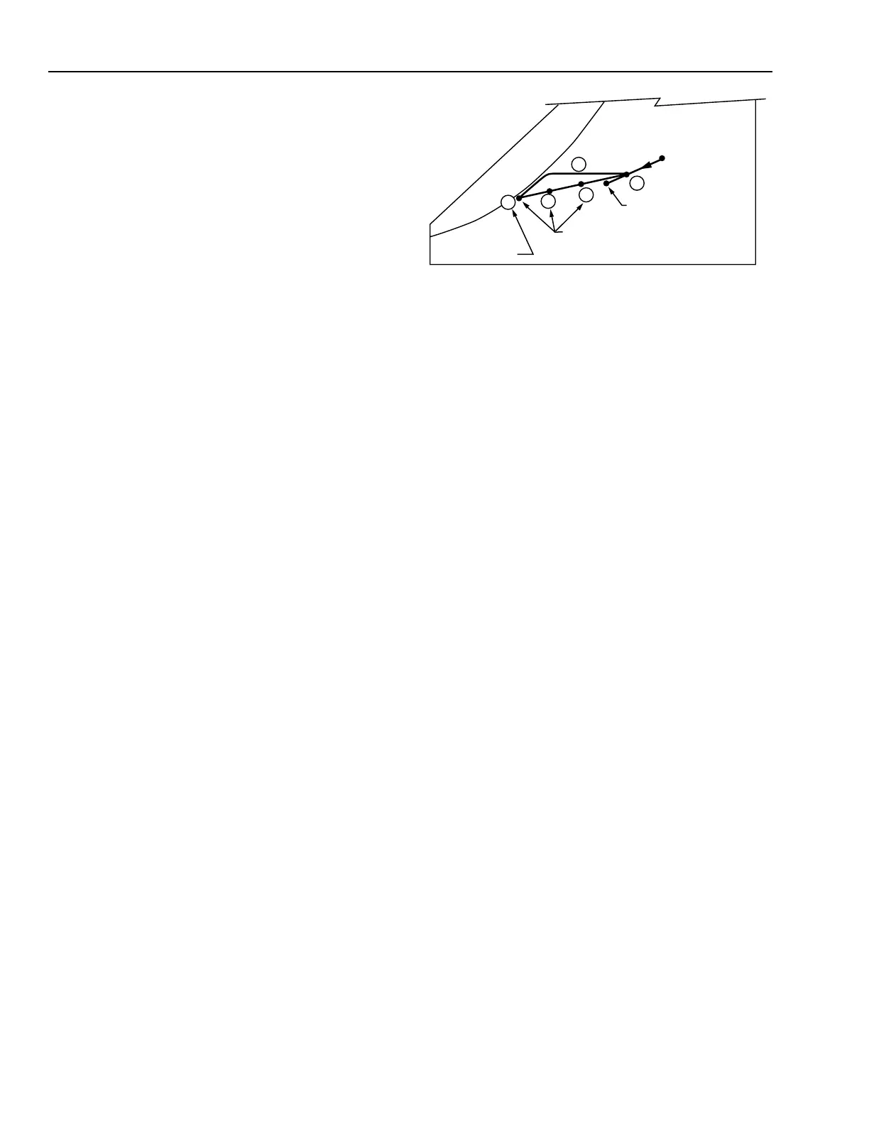
PSYCHROMETRIC ASPECTS
In the following chart it is assumed that:
1. RA condition is 78°F DB and 50% RH (65°F WB).
2. Design OA condition is 95°F DB and 75°F WB.
3. Air entering the system is from the ECONOMIZER
CYCLE DECISION application. The system operates on
35 percent OA during the cooling cycle.
4. One zone is calling for full cooling.
5. Other zones require partial cooling.
6. Coil leaving air temperature is 55°F.
C2561-2
ZONE
SUPPLIES
OA
95°F DB,
75°F WB
RA 78°F DB,
50% RH
3
4
2
5
1
COOLING
COIL
DISCHARGE
55°F DB
MA
The following results are obtained:
Item
No. Explanation
1Mixed air temperature at cooling design
condition.
2Air entering the coil is cooled along a line of
constant moisture content until saturation is
approached. Near saturation the moisture
content is reduced as the air is cooled. This
process involves both latent and sensible
cooling.
3This condition represents the air leaving the
cold deck and air supplied to the zone calling
for full cooling.
4 This condition represents the SA to a zone
with partial call for cooling. Both cooling and
bypass dampers are partially open.
5 This condition represents the SA to a zone
with a partial call for cooling but less than
that at Point 4.