ENGINEERING MANUAL OF AUTOMATIC CONTROL
CHILLER, BOILER, AND DISTRIBUTION SYSTEM CONTROL APPLICATIONS
387
Functional principles:
The primary side consists of the supply and return lines, plus
necessary pressure reducing, regulating, and safety equipment.
This is self-regulating equipment which provides a given
differential pressure, absolute pressure reducing, and safety
close off functions.
The heat regulation unit (Fig. 130) provides the required
temperature by controlling the primary flow (A) or by mixing
the cooled return water with supply water (B). Different
configurations with two and three way valves can be used. In
the flow control configuration a fixed speed circulating pump
increases the pressure in the return line above the supply flow
pressure. In the temperature control configuration either a jet
pump or a three way valve is used.
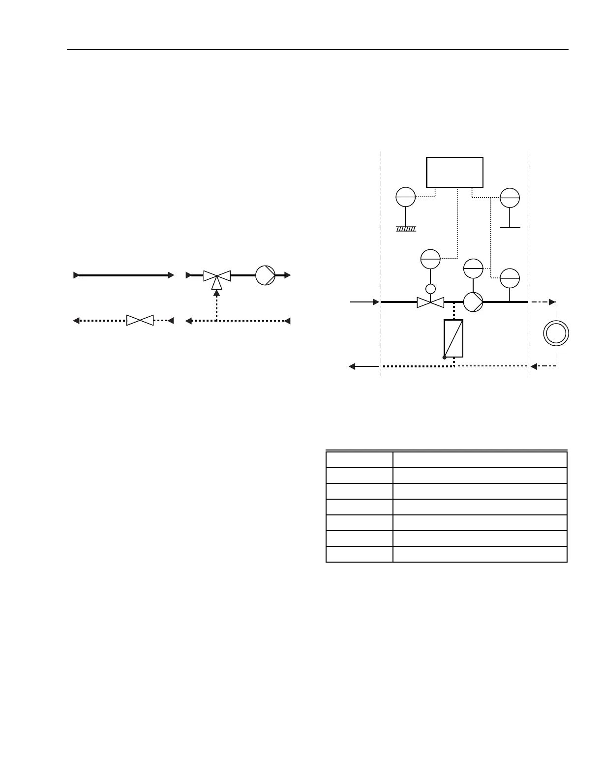
Fig. 131. Small Direct Heat Transfer
Substation for Multiple Family Buildings
Table 9. Description of Figure 131 Reference Points.
Fig. 130. Two- And Three-Way Valve Configurations for a
Heat regulation Unit.
Jet pumps use the effect of injection, making a mechanical
pump unnecessary, thereby, saving electrical energy. However,
adapting and dimensioning jet pump applications to fit operating
conditions is difficult.
Control loops used in a direct substation:
– Supply flow temperature reset on outdoor air temperature.
– Return temperature limit.
–Time schedule functions.
–Night setback and frost protection.
M11446
CONTROL VALVE
CIRCULATING
PUMP
THREE-WAY
MIXING VALVE
OR JET PUMP
A) FLOW CONTROL
B) TEMPERATURE CONTROL
SUPPLY LINE
RETURN LINE
Y
11
M
TC
TI
01
OUTSIDE AIR
TI
31
TIC
13
Y
12
ROOM
CONSUMER
SSF
SRF
PSF
PRF
DISTRIBUTION
M11435
SUBSTATION
Small Substation For Multiple Family Buildings
Figure 131 shows a typical direct heat transfer substation.
Reference Description
TC Controller
TI 01 Outdoor air temperature sensor
TI 31 Room temperature
TIC 13 SSF temperature
Y 11 Actuator control valve PSF
Y 12 Circulating pump