ENGINEERING MANULA OF AUTOMATIC CONTROL
INDIVIDUAL ROOM CONTROL APPLICATIONS
420
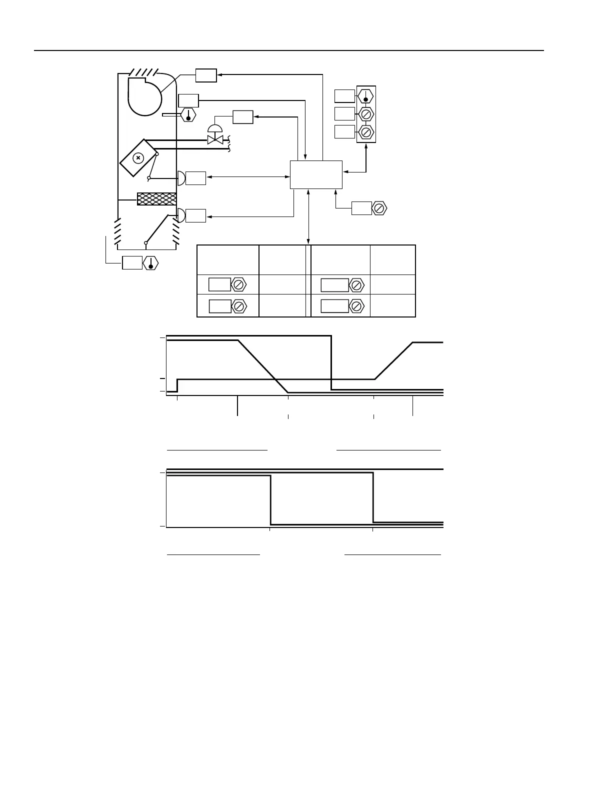
Fig. 28. Cycle II with Enhanced Digital Control.
RA
FAN
M10547
OA
CONTROL
PROGRAM
75
73
46
77
WALL MODULE
75
TEMPERATURE
HEATING
SETPOINT
COOLING
SETPOINT
00
24
00
PERCENT OPEN
TO OUTSIDE AIR
PERCENT OPEN
TO BYPASS
OPEN
CLOSED
MINIMUM
RECIRCULATE
SETPOINT
HEATING
SETPOINT
COOLING
SETPOINT
HEATING LOAD
PERCENT
COOLING LOAD
PERCENT
100 10000
HOT WATER VALVE
HOT WATER VALVE
OUTSIDE AIR
DAMPER
FACE
DAMPER
FAN ON
OCCUPIED MODE
OPEN/ON
CLOSED/OFF
FAN ON
SETPOINT
CONVECTION
SETPOINT
FACE DAMPER
FAN
UNOCCUPIED MODE
OA DAMPER
CLOSED
55
105
0
100
0
100
DISCHARGE
TEMPERATURE
SETPOINT
HEATING
LOAD
PERCENT
COOLING
LOAD
PERCENT
DISCHARGE
TEMPERATURE
SETPOINT
75
55
MINIMUM
VENTILATION
DAMPER
SETPOINT
55
ON
PERCENT
OPEN
On morning occupancy startup, the fan operates with the hot
water valve open, the face damper open, and the OA damper
closed; and as the room warms to a vent/recirculate setpoint,
the OA damper opens to a minimum ventilation position. As
the heating load drops, the face and bypass dampers modulate
to maintain the room heating temperature setpoint. As the room
temperature rises to a value midpoint between the heating and
cooling setpoints, the heating valve closes. If the room
temperature rises to the cooling setpoint, the OA damper
modulates to maintain the cooling setpoint.
Although the discharge air sensor could be used as a low
limit only, Figure 28 shows it as the primary controller reset
from the demands of the room sensor.
In the unoccupied mode, the valve is controlled in a two-
position manner to maintain an unoccupied convection heating
room temperature setpoint. If the room temperature cannot be
maintained by convection heating, the fan is cycled to maintain
the unoccupied heating fan-on setpoint. The face damper is
open and the OA damper is closed.
Figure 29 adds a chilled water coil to Figure 28.