100 Thor VM3 with Microsoft Windows Embedded Compact 7 User Guide
1. Connect the wire from Pin 8 of the cable to the switched side of the Screen Blanking
Box or to a user-supplied switch.
2. Connect the wire from Pin 7 of the cable to the unswitched side of the Screen
Blanking Box or to a user-supplied switch.
3. Connect the D9 serial connector to either COM1 or COM2 serial port on the Thor
VM3 dock.
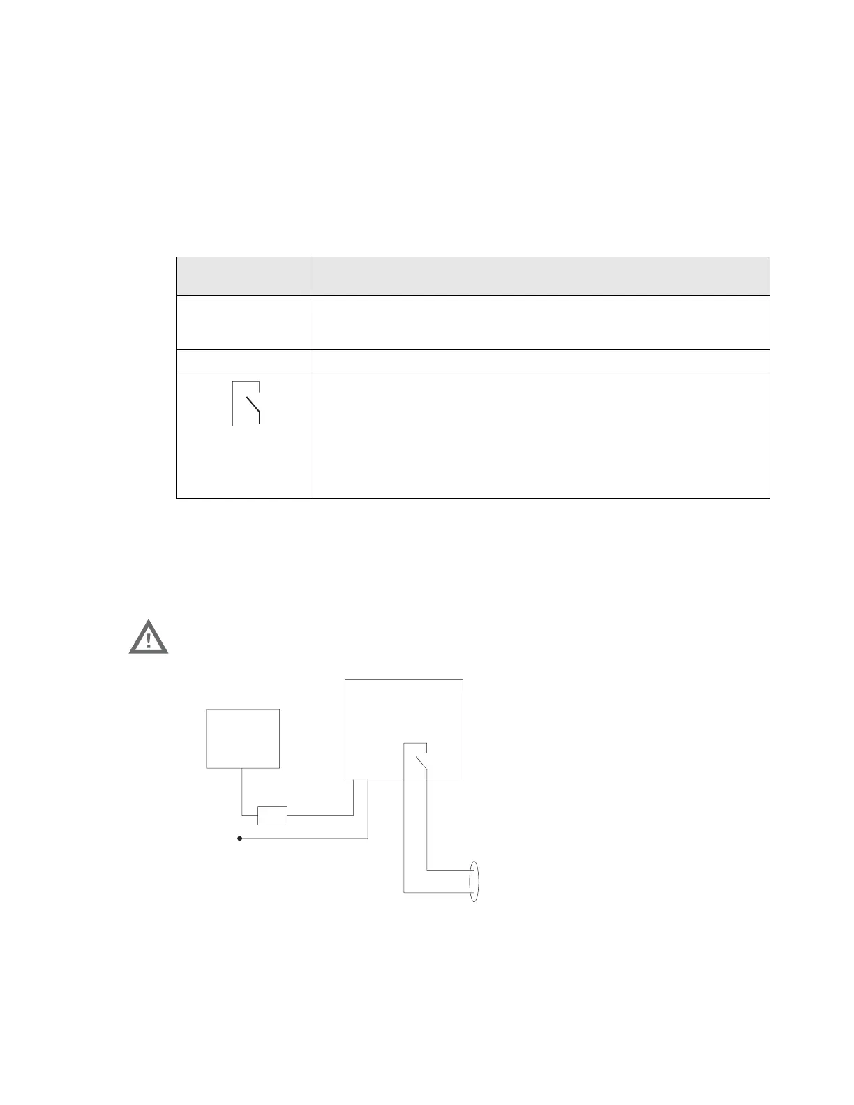
Screen Blanking Box
It is assumed that the motion sensing circuitry in the illustrations below is powered by
internal vehicle circuitry.
Please refer to the appropriate illustration below for Screen Blanking Box wiring dia-
grams.
Note: The black and gray wire colors in the illustration only apply to the optional Honeywell
Screen Blanking Box Cable, VM1080CABLE. The wire colors may be different in a user-
supplied cable.
Screen Blanking
Box Terminal
Connection
12-xxV Input from vehicle motion sensing circuitry.
Please refer to label on Screen Blanking Box for allowable voltage input
range.
GND DC -
These two terminals are for connecting a serial cable:
• If using an optional Honeywell screen blanking cable, VM1080CABLE,
connect the gray wire to the switched side of the connection and connect
the black wire to the unswitched side.
• If using a user-supplied cable, the cable must be constructed so that Pin
7 (RTS) connects to switched side of the connection and Pin 8 (CTS)
connects to the unswitched side.
Warning: Do not exceed the maximum input voltage, either 60 or 72VDC,
specified on the Screen Blanking Box label when using this
configuration.
MOTION
CIRCUITRY
To -Vo on vehicle,
i.e. Negative
battery terminal
3A fuse
+Vi
GND
To pin 7 of COM1 or COM2
To pin 8 of COM1 or COM2

 Loading...