Output Calibration
Procedure
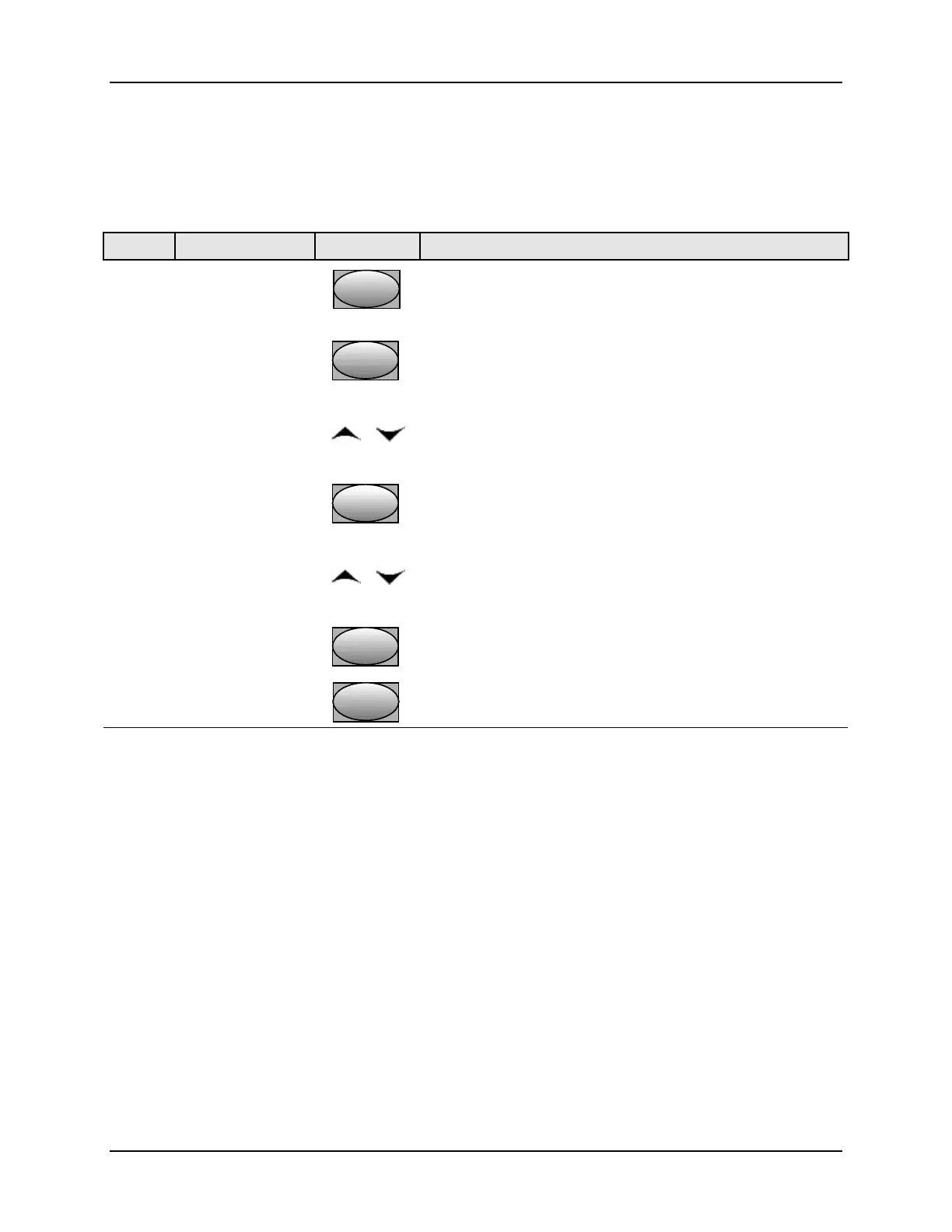
The procedure for calibrating the auxiliary output is listed in Table 6-4.
Make sure “LOCK” in the Tuning Set Up group is set to “NONE” (see Subsection 3.4).
Table 6-4 Auxiliary Output Calibration Procedure
Step Operation Press Result
1
Enter Calibration
Mode
SetupSetup
until you see
Upper Display = CALIB
Lower Display = AUX OUT
2
Calibrate 0 %
Function
FunctionFunction
You will see:
Upper Display = A Value
Lower Display = ZERO VAL
or
until the desired 0 % output is read on the milliammeter.
Normally, this will be the setting that produces 4 mA.
3
Calibrate 100 %
Function
FunctionFunction
To store the 0 % value you will see:
Upper Display = A Value
Lower Display = SPAN VAL
or
until the desired 100 % output is read on the milliammeter.
Normally, this will be the setting that produces 20 mA.
4
Function
FunctionFunction
The controller stores the span value.
Exit the
Calibration Mode
To exit the calibration mode.
Lower
Display
Lower
Display
Lower
Display
12/04 UDC3200 Universal Digital Controller Product Manual 147

 Loading...


