307
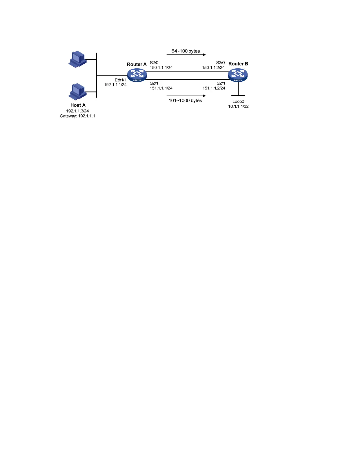
Figure 79 Network diagram
Configuration procedure
1. Configure Router A:
# Configure the IP addresses of the serial interfaces.
<RouterA> system-view
[RouterA] interface serial 2/0
[RouterA-Serial2/0] ip address 150.1.1.1 24
[RouterA-Serial2/0] quit
[RouterA] interface serial 2/1
[RouterA-Serial2/1] ip address 151.1.1.1 24
[RouterA-Serial2/1] quit
# Configure RIP.
[RouterA] rip
[RouterA-rip-1] network 192.1.1.0
[RouterA-rip-1] network 150.1.0.0
[RouterA-rip-1] network 151.1.0.0
[RouterA-rip-1] quit
# Configure Node 10 for policy lab1 to forward packets with a length of 64 to 100 bytes to the
next hop 150.1.1.2, and packets with a length of 101 to 1000 bytes to the next hop 151.1.1.2.
[RouterA] policy-based-route lab1 permit node 10
[RouterA-pbr-lab1-10] if-match packet-length 64 100
[RouterA-pbr-lab1-10] apply next-hop 150.1.1.2
[RouterA-pbr-lab1-10] quit
[RouterA] policy-based-route lab1 permit node 20
[RouterA-pbr-lab1-20] if-match packet-length 101 1000
[RouterA-pbr-lab1-20] apply next-hop 151.1.1.2
[RouterA-pbr-lab1-20] quit
# Configure interface PBR by applying policy lab1 to Ethernet 1/1.
[RouterA] interface ethernet 1/1
[RouterA-Ethernet1/1] ip address 192.1.1.1 24
[RouterA-Ethernet1/1] ip policy-based-route lab1
[RouterA-Ethernet1/1] quit
2. Configure Router B:
# Configure the IP addresses of the serial interfaces.
<RouterB> system-view
[RouterB] interface serial 2/0

 Loading...


