390
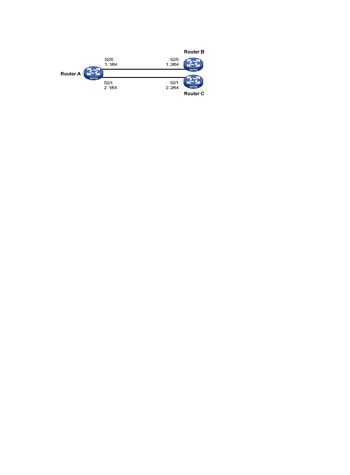
Figure 94 Network diagram
Configuration procedure
1. Configure Router A:
# Configure the IPv6 addresses of the serial interfaces.
<RouterA> system-view
[RouterA] interface serial 2/0
[RouterA-Serial2/0] ipv6 address 1::1 64
[RouterA-Serial2/0] quit
[RouterA] interface serial 2/1
[RouterA-Serial2/1] ipv6 address 2::1 64
[RouterA-Serial2/1] quit
# Configure ACL 3001 to match TCP packets.
[RouterA] acl ipv6 number 3001
[RouterA-acl6-adv-3001] rule permit tcp
[RouterA-acl6-adv-3001] quit
# Configure Node 5 for policy aaa to forward TCP packets to next hop 1::2.
[RouterA] ipv6 policy-based-route aaa permit node 5
[RouterA-pbr6-aaa-5] if-match acl 3001
[RouterA-pbr6-aaa-5] apply next-hop 1::2
[RouterA-pbr6-aaa-5] quit
# Configure IPv6 local PBR by applying policy aaa to Router A.
[RouterA] ipv6 local policy-based-route aaa
2. On Router B, configure the IPv6 address of the serial interface.
<RouterB> system-view
[RouterB] interface serial 2/0
[RouterB-Serial2/0] ipv6 address 1::2 64
3. On Router C, configure the IPv6 address of the serial interface.
<RouterC> system-view
[RouterC] interface serial 2/1
[RouterC-Serial2/1] ipv6 address 2::2 64
Verifying the configuration
# Telnet to Router B on Router A. The operation succeeds.
# Telnet to Router C on Router A. The operation fails.
# Ping Router C from Router A. The operation succeeds.
Telnet uses TCP, and ping uses ICMP. The preceding results show that all TCP packets sent from Router A
are forwarded to the next hop 1::2, and other packets are forwarded through Serial 2/1. The IPv6 local
PBR configuration is effective.

 Loading...


