38
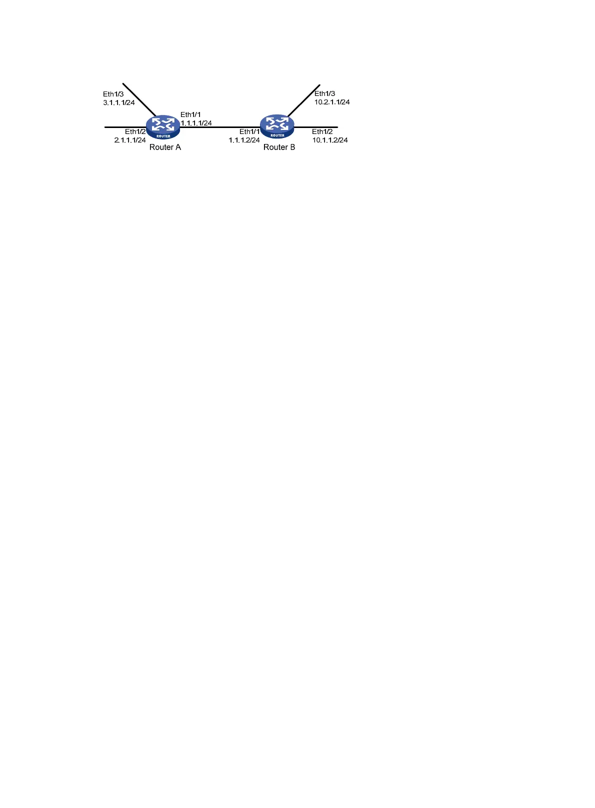
Figure 7 Network diagram
Configuration procedure
1. Configure IP addresses for interfaces. (Details not shown.)
2. Configure basic RIP by using either of the following methods:
(Method 1) # Enable RIP on the specified networks on Router A.
<RouterA> system-view
[RouterA] rip
[RouterA-rip-1] network 1.0.0.0
[RouterA-rip-1] network 2.0.0.0
[RouterA-rip-1] network 3.0.0.0
[RouterA-rip-1] quit
(Method 2) # Enable RIP on the specified interfaces on Router B.
<RouterB> system-view
[RouterB] rip
[RouterB-rip-1] quit
[RouterB] interface ethernet 1/1
[RouteB-Ethernet1/1] rip 1 enable
[RouterB-rip-1] quit
[RouterB] interface ethernet 1/2
[RouteB-Ethernet1/2] rip 1 enable
[RouterB-rip-1] quit
[RouterB] interface ethernet 1/3
[RouteB-Ethernet1/3] rip 1 enable
[RouterB-rip-1] quit
# Display the RIP routing table on Router A.
[RouterA] display rip 1 route
Route Flags: R - RIP
A - Aging, S - Suppressed, G - Garbage-collect
O - Optimal, F - Flush to RIB
----------------------------------------------------------------------------
Peer 1.1.1.2 on Ethernet1/1
Destination/Mask Nexthop Cost Tag Flags Sec
10.0.0.0/8 1.1.1.2 1 0 RAOF 9
The output shows that RIPv1 uses natural masks to advertise routing information.
3. Configure a RIP version:
# Configure RIPv2 on Router A.
[RouterA] rip
[RouterA-rip-1] version 2
[RouterA-rip-1] undo summary
[RouterA-rip-1] quit

 Loading...


