Appendix E
I/O Backplane Pinout
Data
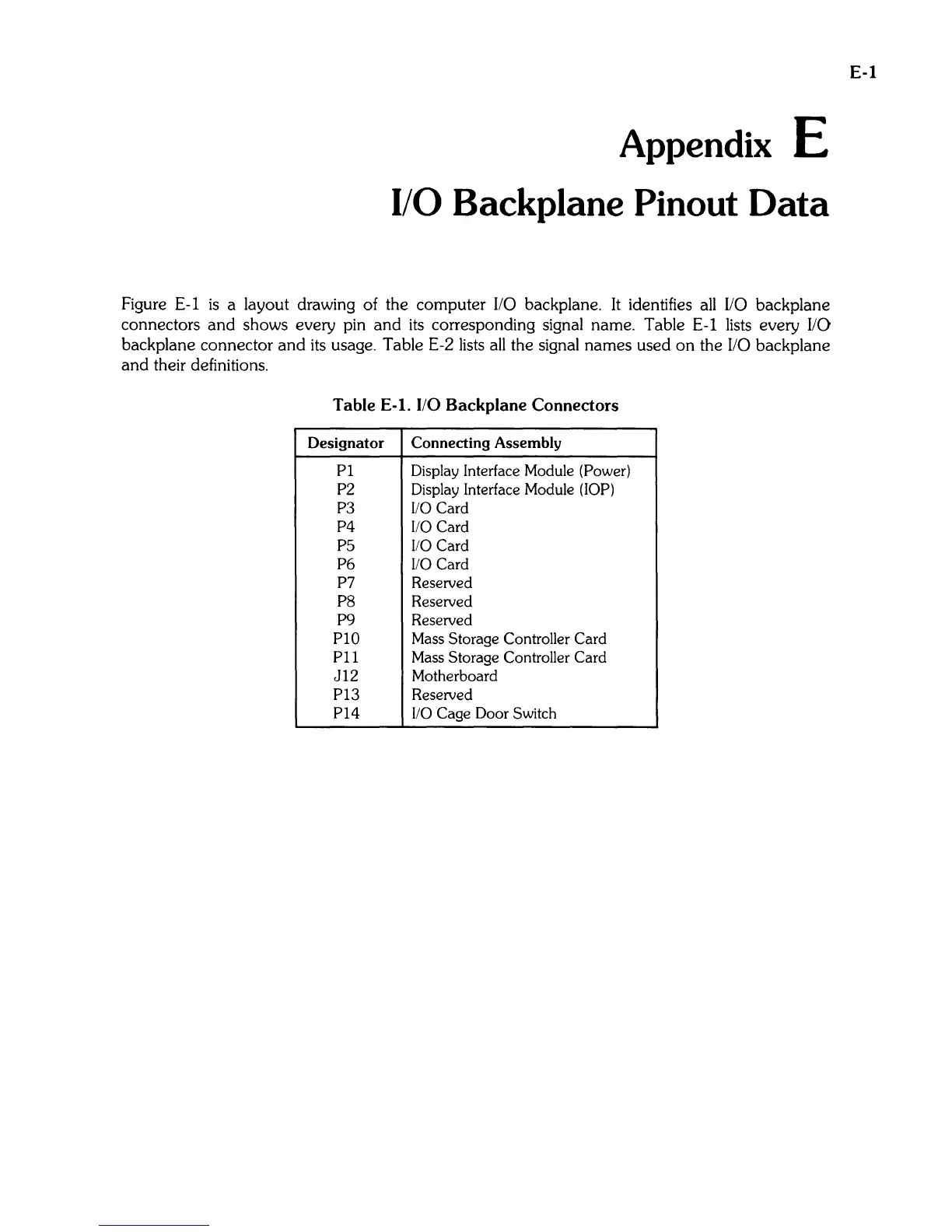
Figure E-l
is
a layout drawing of the computer
110
backplane. It identifies all
110
backplane
connectors
and
shows every pin
and
its
corresponding signal name. Table E-l lists every liD
backplane connector
and
its usage. Table E-2 lists
all
the signal
names
used
on
the
110
backplane
and
their definitions.
Table E-l. I/O Backplane Connectors
Designator Connecting Assembly
PI
Display Interface Module (Power)
P2
Display Interface Module (lOP)
P3
110
Card
P4
110
Card
P5
110
Card
P6
110
Card
P7
Reserved
P8
Reserved
P9
Reserved
PIO Mass Storage Controller Card
PII
Mass Storage Controller Card
JI2
Motherboard
PI3
Reserved
PI4
110
Cage Door Switch
E-l