4-40
Assembly
Access
CAUTION
WHEN PERFORMING THE NEXT
STEP,
ENSURE
THAT PRINT-
HEAD ASSEMBLY
DOES
NOT DAMAGE MOTOR
DRIVE
BOARD
BY SLIPPING OUT OF POSITION
AND FALLING AGAINST
BOARD.
DO NOT TOUCH PRINTHEAD
RESISTOR
AREA.
DAMAGE TO
THE PRINTHEAD COULD
RESULT.
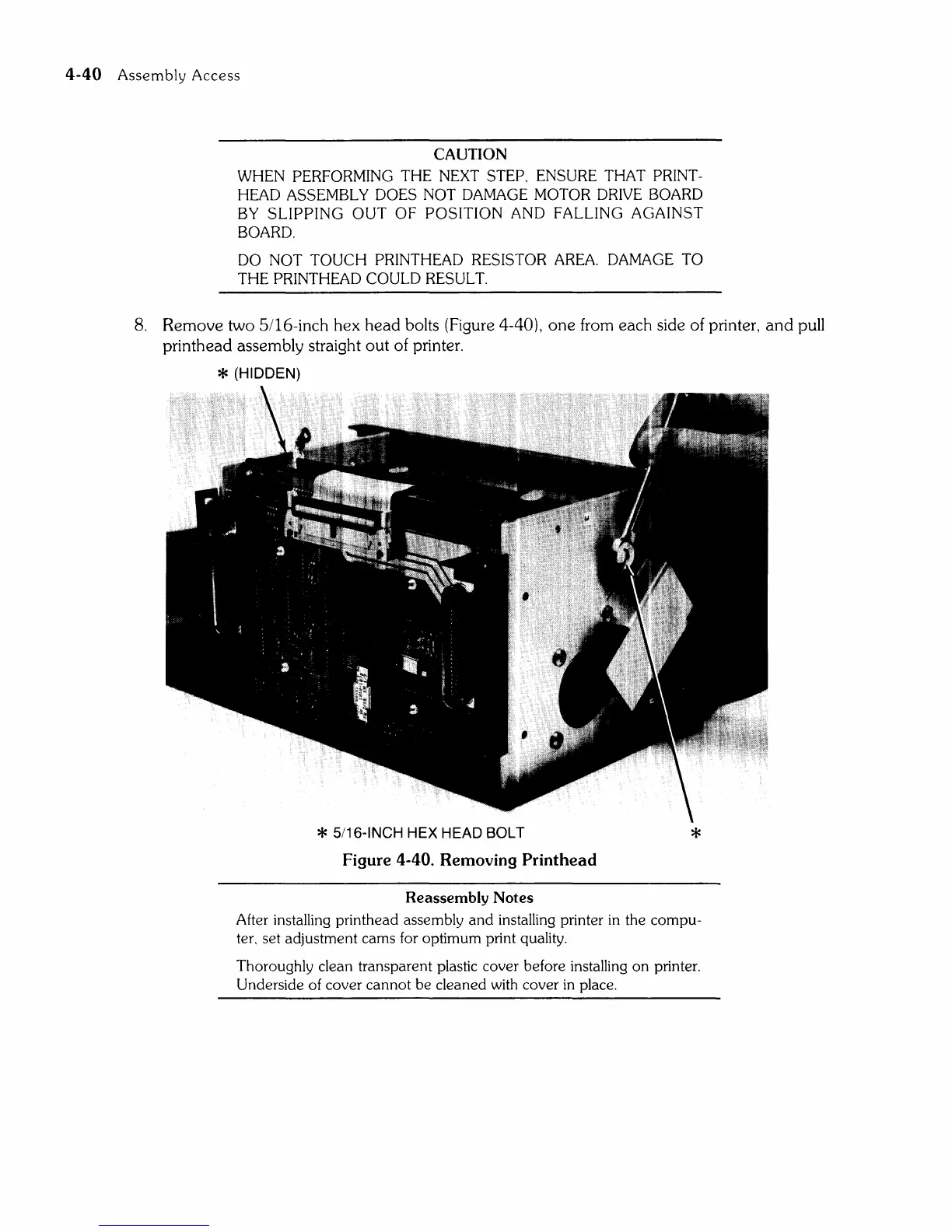
8.
Remove
two 5/16-inch hex
head
bolts (Figure 4-40),
one
from each side of printer,
and
pull
printhead assembly straight
out
of printer.
* (HIDDEN)
* 5/16-INCH HEX HEAD BOLT
*
Figure 4-40. Removing Printhead
Reassembly
Notes
After installing printhead assembly
and
installing printer
in
the
compu-
ter, set adjustment cams for optimum print quality.
Thoroughly clean transparent plastic cover before installing
on
printer.
Underside of cover
cannot
be
cleaned with cover
in
place.