Assembly
Access
4-41
Printhead Assembly Access
The following procedure provides access to heat sinks, head backing plate, chip modules, printhead
interconnect board,
and
the printhead.
CAUTION
DO NOT TOUCH PRINTHEAD RESISTOR AREA WHEN PERFORM-
ING
THE
FOLLOWING
PROCEDURE OR DAMAGE TO
THE
PRINTHEAD COULD RESULT.
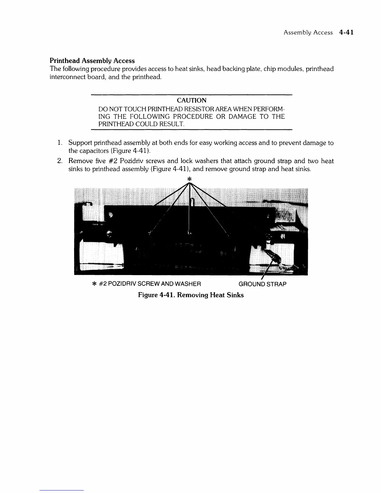
1.
Support printhead assembly at both ends for easy working access and to prevent damage to
the capacitors (Figure 4-41).
2.
Remove
five
#2
Pozidriv screws and lock washers that attach ground strap
and
two heat
sinks to printhead assembly (Figure 4-41), and remove ground strap
and
heat sinks.
*
*
#2
POZIDRIV SCREW AND WASHER
GROUND STRAP
Figure 4-41. Removing Heat Sinks