Theory
of
Operation 2-53
16-BIT
1
8K
BYTES
LOADER
I--
COUNTER
,
ROM
CONTROL
~
LOGIC
1
f
.....
~
I
,
STS/FLG
ID
....
~
~
l
J
BUFFER
I J
BUFFER
I I
BUFFER
I
I
I I
J
I
f
lOP
BUS
f
----------
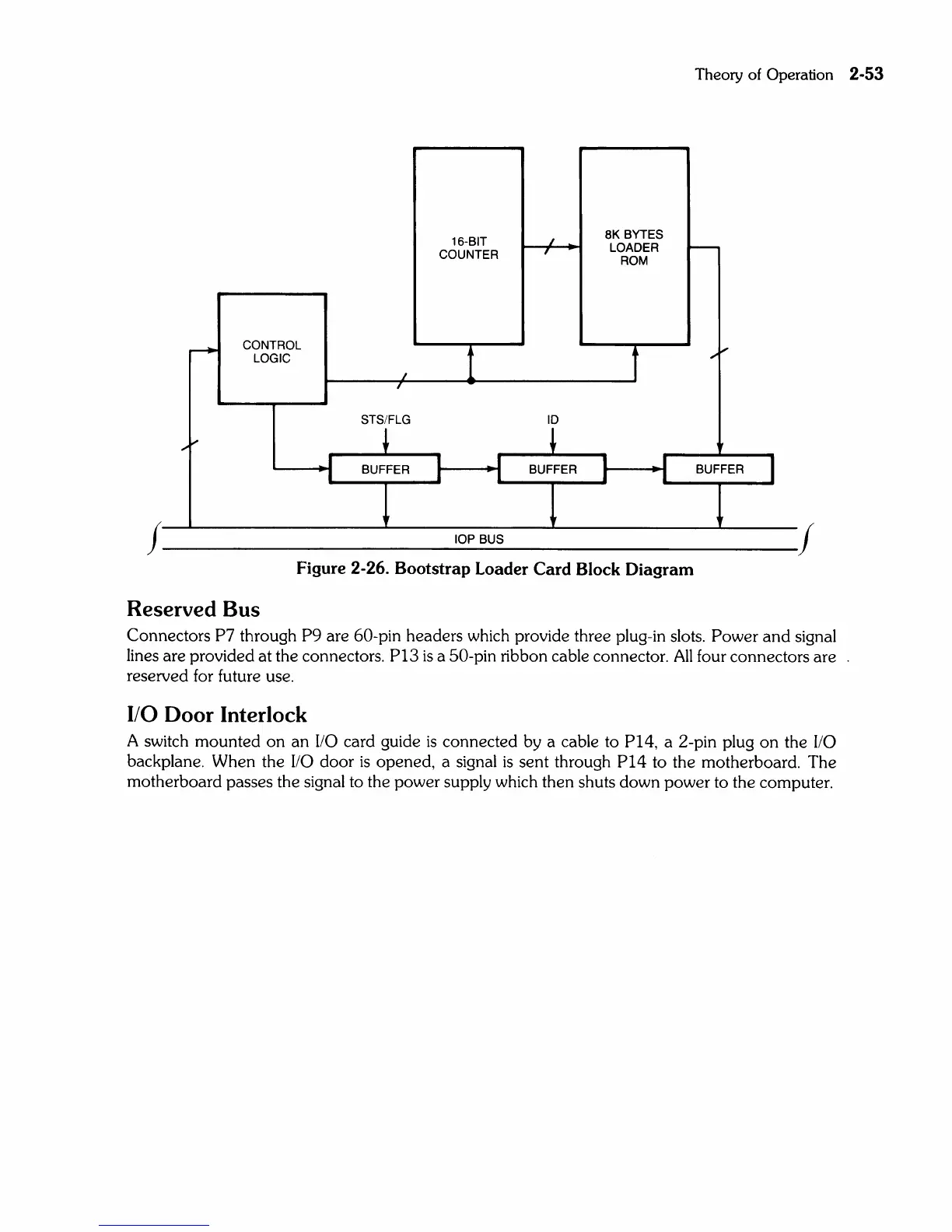
Figure 2-26. Bootstrap Loader Card Block Diagram
Reserved
Bus
Connectors P7 through
P9
are 60-pin headers which provide three plug-in slots. Power
and
signal
lines are provided at the connectors.
P13
is
a 50-pin ribbon cable connector.
All
four connectors are
reserved for future use.
I/O Door Interlock
A switch mounted
on
an
110
card
gUide
is
connected by a cable to P14, a 2-pin plug
on
the
110
backplane. When the
110
door
is
opened, a signal
is
sent through
P14
to the motherboard. The
motherboard passes the signal to the power supply which then shuts down power to the computer.