Assembly
Access
4-25
4.
Loosen two
#2
Pozidriv screws that hold trim piece to left side of computer (Figure 4-19) just
far enough to remove trim piece. Remove trim piece while leaving screws
in
place
on
computer.
5. Disconnect
lOP expander cables,
if
present, from processor stack door (Figure 4-17).
6.
Loosen two
#2
Pozidriv captive screws at bottom of processor stack door (Figure 4-20).
CAUTION
BEFORE REMOVING PROCESSOR STACK DOOR
AS
DESCRIBED
IN THE
FOLLOWING STEP, NOTE
THAT
INTERNAL lOP EXPAND-
ER
CABLES MAY INTERCONNECT THE DOOR WITH ADDITION-
AL
lOP FINSTRA
TES.
THESE CABLES MUST BE DISCONNECTED
FROM
THE
FINSTRA TES BEFORE THE DOOR CAN BE COM-
PLETEL Y REMOVED.
7.
Loosen two captive thumbscrews
on
processor stack door (Figure 4-20)
and
remove door.
Disconnect internal
lOP expander cable(s),
if
present, from lOP finstrate(s) (Figure 4-21).
8. Disconnect internal
lOP cable from lOP finstrate
in
slot
#2
(Figure 4-21).
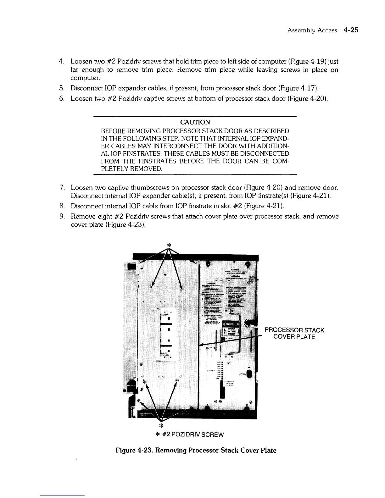
9.
Remove eight
#2
Pozidriv screws that attach cover plate over processor stack,
and
remove
cover plate (Figure 4-23).
*
I'!i.
•.
I--
t '
f •
I--
~4
'i" •
*
::~:
'.\
;,~!I<:
•
,we.
"(~.
,,~.
,y.;:,(".
;;;"1.,
;
..
,",,~
I"~~
~~
*
#2
POZIDRIV SCREW
PROCESSOR STACK
COVER
PLATE
Figure 4-23. Removing Processor
Stack
Cover Plate