lOP
Theory
of
Operation 2-49
The
110
card has a 16-deep FIFO (first-in, first-out) buffer
in
order to enable byte-burst
DMA.
In
the
DMA-out direction, the
lOP byte-bursts data into the FIFO. The FIFO
is
then conditioned so that
the microprocessor or disc controller can read the data
out
of
it.
When the FIFO
is
empty,
it
is
again
conditioned so the
lOP can
refill
it.
For a
DMA-in
operation, the microprocessor
or
disc controller
fills
the FIFO. The FIFO
is
then conditioned so the data can be byte-burst into the lOP.
The FIFO manager consists of a 16-bit bi-directional shift register which monitors the contents of
the
FIFO during a burst transfer. This enables the logic to deassert burst request
(BR)
at the right
time
and
avoid data overrun or underrun.
The message register enables the
lOP to inform the disc controller of the type of transaction to be
performed. The control register allows the microprocessor to control the
lOP interface logic
and
the
FIFO manager.
The
8039
microprocessor operates at
10
MHz,
has
128
bytes of internal
RAM,
and
supports
up
to
4K byres in
an
8K-byte external program
ROM.
The microprocessor
1)
performs a self test of the
interface after a reset, 2) performs the boot load function for the computer (including
10 ROM
operation for protectiion of software rights), 3) sends command/data information to/from the disc
controller
per
the commands from the lOP, 4) enables/disables the
DMA
control logic that permits
data to
be
DMA'
ed
directly between the disc controller
and
the FIFO,
and
5) controls the FIFO
manager via the control register/message register.
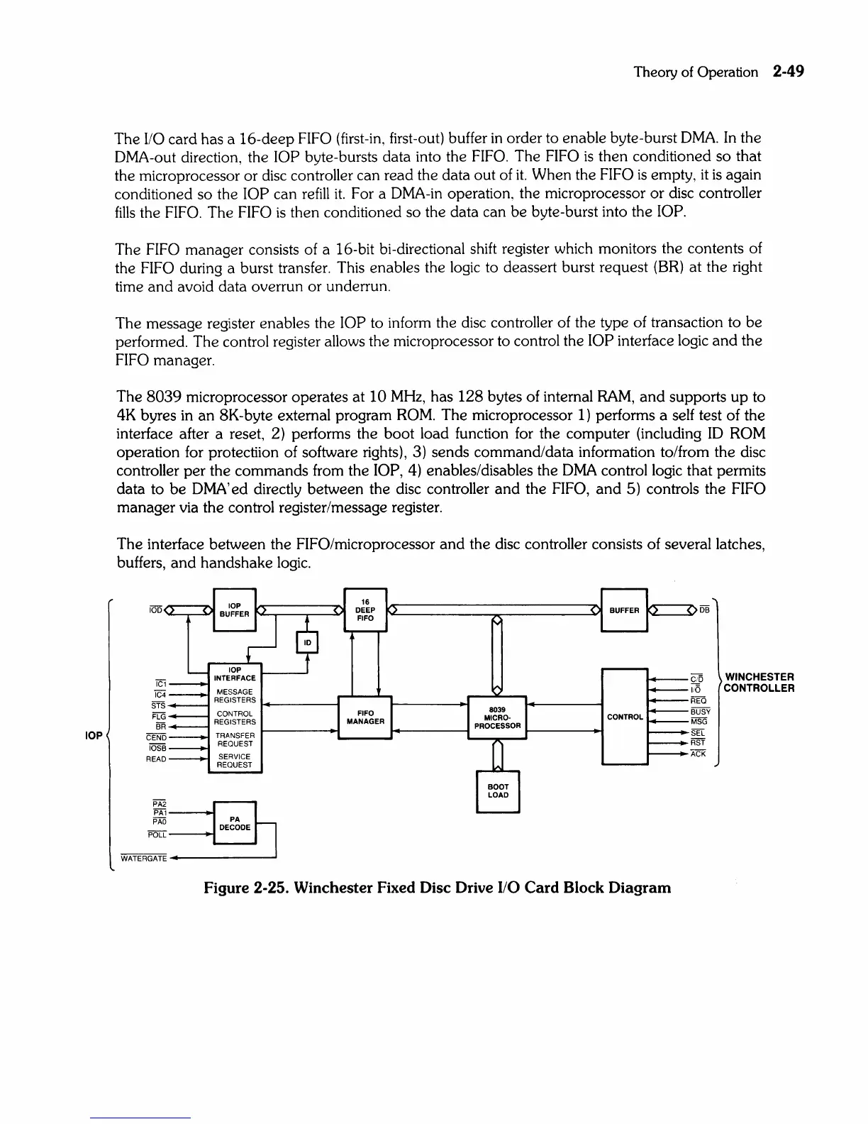
The interface between the FIFO/microprocessor
and
the disc controller consists of several latches,
buffers,
and
handshake logic.
100
<>
<
I....-
1_
iC
iC
STS
FLG
4_
i
__
:--
BR
CENO
IOS8
READ
,-
-
-
lOP
BUFFE~
lOP
INTERFACE
MESSAGE
REGISTERS
CONTROL
REGISTERS
TRANSFER
REQUEST
SERVICE
REOUEST
2
1
PA~
PA
PAD
PA
____
DECODE
POLL
WATERGATE
16
<
DEEP
~
<
BUFFER
:>
$
FIFO
.....
'"
FIFO
8039
MANAGER
MICRO·
CONTROL
PROCESSOR
BOOT
LOAD
Figure 2-25. Winchester Fixed Disc Drive I/O Card Block Diagram
<
CI
is
WINCHESTER
II
6 CONTROLLER
EO
R
""""iJSv
8
SG
M
EL
S
Sf
R
CK
A