lOP
Theory of Operation
2-47
The flexible disc controller card shares select code 7 with either the fixed disc controller assembly or
bootstrap loader card. Circuitry
on
the fixed disc controller assembly
or
bootstrap loader card
switches between the assembly or card
and
the flexible disc controller card. Only
one
of the select
code 7 assembly/cards
is
activated at
one
time. The lOP controls the select code sharing logic by
setting or clearing bit 8 in register 8. A dedicated backplane signal indicates whether
or
not the
flexible disc controller card
is
activated.
Motherboard connectors
J53
and
J54
provide power
and
ground signals to the flexible disc drive
and/or fixed disc drive.
An
"N"
preceding
a signal
name
in the following text
corresponds
to
an
overbar
in
the
diagram;
both
indicate a negative true condition.
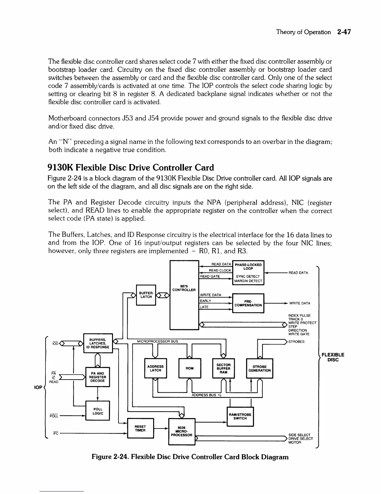
9130K Flexible Disc Drive Controller
Card
Figure
2-24
is
a block diagram of the 9130K Flexible Disc Drive controller card.
All
lOP signals are
on
the left side of the diagram,
and
all
disc signals are
on
the right side.
The
PA
and
Register
Decode
circuitry inputs
the
NPA (peripheral address), NIC (register
select),
and
READ lines to
enable
the appropriate register
on
the
controller
when
the
correct
select
code
(PA state)
is
applied.
The
Buffers, Latches,
and
ID
Response
circuitry
is
the
electrical interface for
the
16
data
lines
to
and
from
the
lOP.
One
of
16
input/output
registers
can
be
selected by
the
four NIC lines;
however, only
three
registers
are
implemented
-
RO,
Rl,
and
R3.
10D
PA
iC
READ
0
}
(
-
READ DATA
PHASE·LOCKED
READ CLOCK
LOOP
READ GATE
SYNC DETECT
MARGIN DETECT
8876
CONTROLLER
~
BUFFERI
~
LATCH
WRITE DATA
EARLY
PRE·
LATE
COMPENSATION
.)
BUFFERS,
~
MICROPROCESSOR BUS
LATCHES,
U
lJ
b
10
RESPONSE
~
[J
IAI
ADDRESS
SECTOR
STROBE
LATCH
ROM
BUFFER
GENERATION
PAAND
RAM
REGISTER
DECODE
l
n
nt
tr]
!
ADDRESS BUS 1
~
I I
POLL
~
LOGIC
RAM/STROBE
SWITCH
~
RESET
-----..
8039
TIMER
MICRO·
PROCESSOR
~
()
)
)
READ DATA
WRITE DATA
I
NDEX PULSE
TRACK 0
WRITE
PROTECT
STEP
DIRECTION
WRITE
GATE
STROBES
SIDE SELECT
DRIVE SELECT
MOTOR
Figure 2-24. Flexible Disc Drive Controller
Card
Block
Diagram
FLEXIBLE
DISC