Theory
of
Operation
2-29
lOP Bus
The 50-conductor lOP ribbon cable interconnects the motherboard with the lOP finstrate
in
slot
#2.
The lOP finstrate handles internal peripherals as
well
as the
110
backplane. With eight select
codes per
lOP
and
a
full
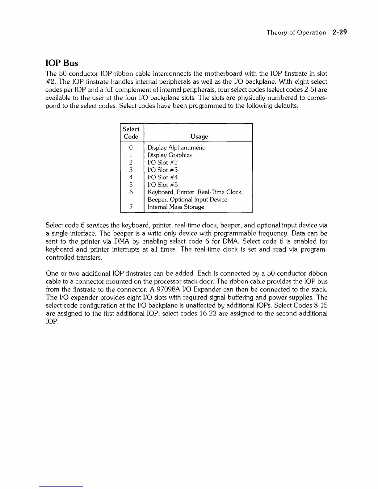
complement of internal peripherals, four select codes (select codes 2-5) are
available to the user at the four
110
backplane slots. The slots are physically numbered to corres-
pond
to the select codes. Select codes have
been
programmed to the following defaults:
Select
Code
Usage
0
Display Alphanumeric
1
Display Graphics
2
110
Slot
#2
3
110
Slot
#3
4
110
Slot
#4
5
110
Slot
#5
6
Keyboard, Printer, Real-Time Clock,
Beeper, Optional Input Device
7
Internal Mass Storage
Select code 6 services the keyboard, printer, real-time clock, beeper,
and
optional input device via
a single interface. The beeper
is
a write-only device with programmable frequency. Data can be
sent to the printer via
DMA
by enabling select code 6
for
DMA.
Select code 6
is
enabled for
keyboard
and
printer interrupts at
all
times. The real-time clock
is
set
and
read via program-
controlled transfers.
One
or
two additional lOP finstrates can be added. Each
is
connected by a 50-conductor ribbon
cable to a connector mounted
on
the processor stack door. The ribbon cable provides the lOP bus
from the finstrate to the connector. A
97098A
110
Expander can then be connected to the stack.
The
110
expander
provides eight
110
slots with required signal buffering
and
power supplies. The
select code configuration at the
110
backplane
is
unaffected by additional lOPs. Select
Codes
8-15
are assigned to the
first
additional lOP; select codes 16-23 are assigned to the second additional
lOP.