4-36
Assembly
Access
Language
Resistors
To change the language configuration of the keyboard, perform the following procedures:
1.
UNPLUG COMPUTER POWER CORD FROM
AC
OUTLET.
2.
Remove keyboard from computer as previously described.
3.
Place keyboard upside down
on
an
antistatic surface (Figure 4-33).
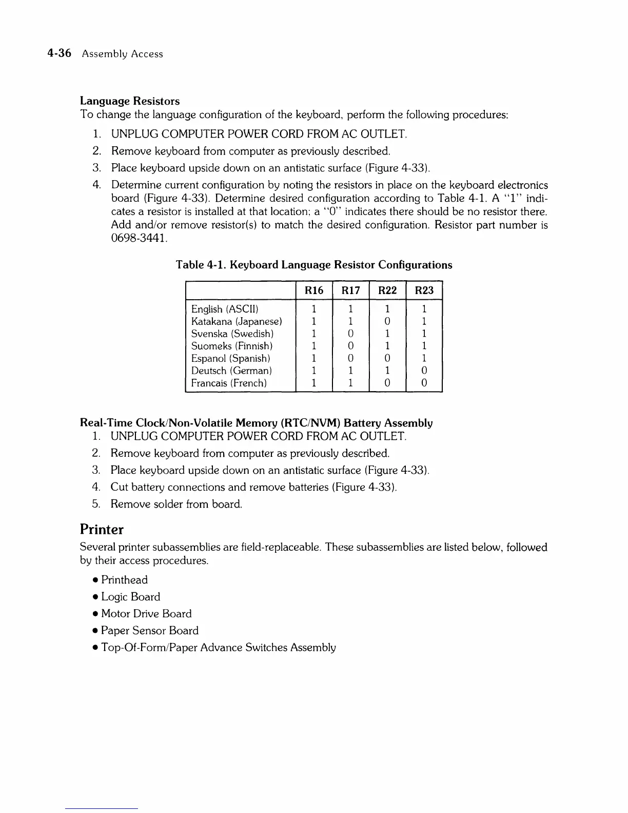
4.
Determine current configuration by noting the resistors
in
place
on
the keyboard electronics
board
(Figure 4-33). Determine desired configuration according to Table 4-1. A
"I"
indi-
cates a resistor
is
installed at that location; a
"0"
indicates there should
be
no resistor there.
Add and/or remove resistor(s) to match the desired configuration. Resistor part
number
is
0698-3441.
Table
4-1. Keyboard
Language
Resistor
Configurations
R16
R17
R22
R23
English (ASCII)
1
1 1 1
Katakana
(Japanese)
1 1 0 1
Svenska
(Swedish)
1 0
1 1
Suameks
(Finnish)
1 0 1 1
Espanal
(Spanish)
1 0 0
1
Deutsch (German)
1
1 1
0
Francais (French)
1
1
0 0
Real-Time Clock/Non-Volatile
Memory
(RTC/NVM)
Battery
Assembly
1.
UNPLUG COMPUTER POWER CORD FROM
AC
OUTLET.
2.
Remove keyboard from computer as previously described.
3.
Place keyboard upside down
on
an
antistatic surface (Figure 4-33).
4.
Cut battery connections
and
remove batteries (Figure 4-33).
5.
Remove solder from board.
Printer
Several printer subassemblies are field-replaceable. These subassemblies are listed below, followed
by their access procedures.
• Printhead
•
Logic Board
• Motor Drive Board
•
Paper
Sensor
Board
• Top-Of-Form/Paper Advance Switches Assembly