4-18
Assembly Access
Bootstrap
Loader
Card
Perform preceding procedures for Mass Storage Controller Cards. Step 7 does not require removal
of cable connector(s}.
CAUTION
REMOVE THE LOADER/ID ROM FROM THE OLD CARD AND IN-
STALL IT
ON THE NEW CARD, WHEN REPLACING THE BOOT-
STRAP LOADER
CARD.
USE
TOOL 8710-0585.
IF
ORDERING A
NEW
10 ROM, THE SERIAL NUMBER
OF
THE COMPUTER MUST
BE
PROGRAMMED INTO THE REPLACEMENT
10
ROM.
SEE
THE
REPLACEMENT PARTS LIST FOR THE CORRECT ROM PART
NUMBER.
Processor
Stack
Several processor stack subassemblies are field-replaceable. These subassemblies, except the fan,
are listed below, followed by their access procedures. Fan access procedures follow
in
this chapter.
• Boards
• Clock Board
• Motherboard
Stack
Boards
The processor stack has 12 slots. Access to the lower three slots requires procedures that differ from
those necessary to gain access to the upper nine slots. Both procedures are documented below.
Slots 4-12
1.
UNPLUG COMPUTER POWER CORD FROM
AC
OUTLET.
2.
Open
left side door as previously described.
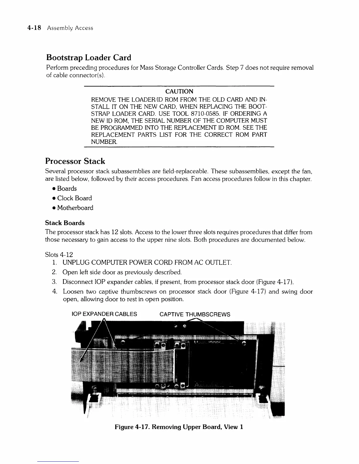
3.
Disconnect lOP expander cables, if present, from processor stack door (Figure 4-17).
4.
Loosen two captive thumbscrews
on
processor stack door (Figure 4-17)
and
swing door
open, allowing door to rest
in
open
position.
lOP EXPANDER CABLES
CAPTIVE THUMBSCREWS
Figure
4-17.
Removing Upper Board, View 1