System LEDs and Switches
Battery-Backed Write Cache Enabler
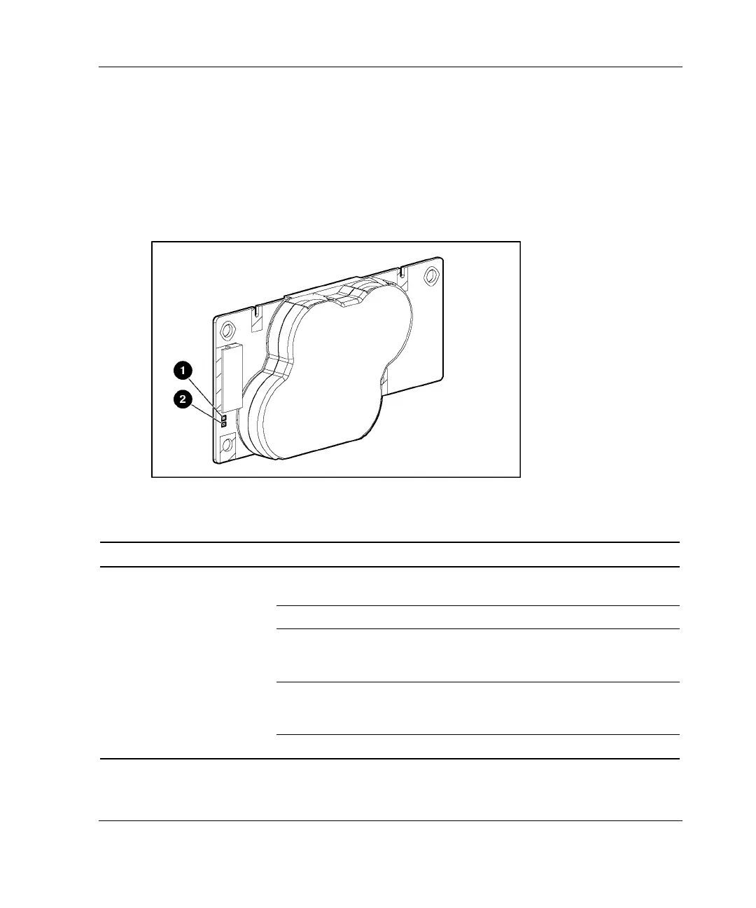
When the BBWCE is connected to the controller and the server is powered on, the
green LED indicates the status of the battery charge. When the battery is connected to
the controller and the server is powered down, the amber LED indicates the status of
the data retention. Use Figure E-8 and Table E-12 to identify the location and status
of each of the LEDs.
Figure E-8: BBWCE LEDs
Table E-12: BBWCE LEDs
Server Status LED Color LED Status Battery Module Status
Server is on and has
normal run time
Green On Fast charging
Green Off Trickle-charging
Amber On Short in the connection of one or
more of the four button cells
within the battery module
Amber Blinking Open in the circuit between the
positive and negative terminals of
the battery module
Amber Off Battery module status is normal
continued
HP ProLiant DL580 Generation 2 Server Setup and Installation Guide E-13
HP CONFIDENTIAL
Writer: Karen Hale File Name: p-appe System LEDs and Switches3.doc
Codename: Wave Part Number: 230835-003 Last Saved On: 6/26/03 9:49 AM

 Loading...