PORT PROCESSORS/MODULES
940043-002 INTEGRATED ENTERPRISE NETWORK 3-29
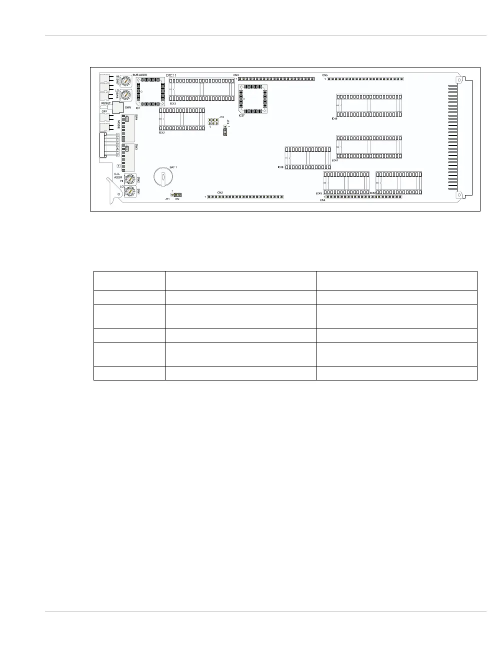
Figure 3-26 illustrates the jumper locations for the DTC11-LHO/E1 port processor.
Figure 3-26 DTC11-LHO/E1 Jumper Locations
Table 3-9 lists the jumper definitions for the DTC11-LHO/E1 port processor.
Table 3-9 DTC11-LHO/E1 Jumper Definitions
JUMPER DESCRIPTION FACTORY SETTING
JT1 Battery On/Off Battery On: Pins 2 & 3 connected.
JT2 SCC Clock 6/12/19MHz
6MHz: Pins 1 & 2 connected.
Do not change setting.
JT3 Do not connect.
JT4 CPU Clock 6/12MHz
6MHz: Pins 1 & 2 connected.
Do not change setting.
JT5 Do not connect.