EasyManuals Logo

Hypertherm Powermax30 AIR Service Manual

Hypertherm Powermax30 AIR
223 pages
To Next Page IconTo Next Page
To Previous Page IconTo Previous Page
Page #122 background imageLoading...
Page #122 background image
122 Powermax30 AIR Service Manual 808850
6 Power Supply Component Replacement
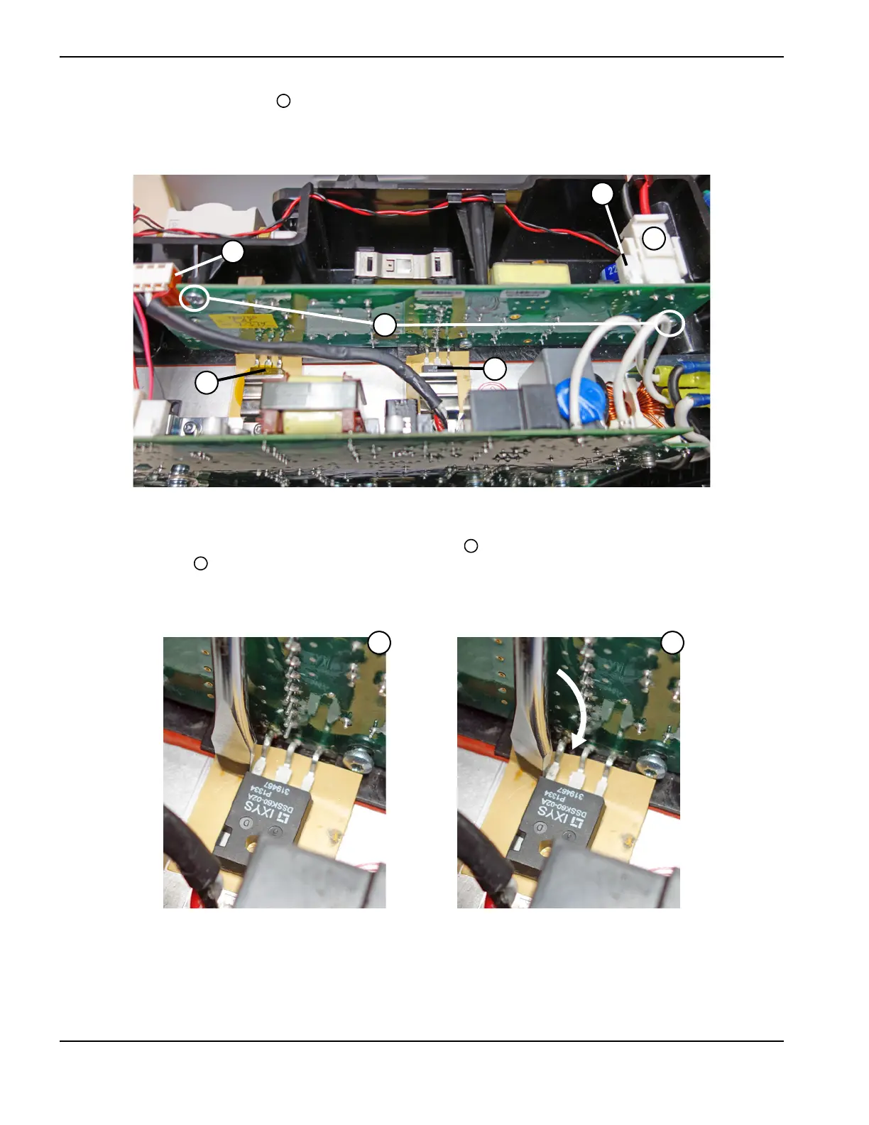
5. Remove the 2 retaining screws from the left side and right side of the compressor-driver board.
Figure 42
6. Being careful not to scratch the heatsink, position the head of a large blade screwdriver so that it is parallel to the top
edge of the diode and next to the diode’s curved metal prongs . Slowly twist the screwdriver so that it pushes
against the diode . Continue twisting until the diode breaks free from the thermal strip.
Figure 43
7. Repeat the previous step to detach the MOSFET from its thermal strip.
8. Make sure the MOSFET and diode are fully detached from the heatsink. Lift the compressor-driver board out of the
power supply.
7
J
3
J
2
J
1
4
5
7
8
9
8 9

Table of Contents

Other manuals for Hypertherm Powermax30 AIR

Questions and Answers:

Question and Answer IconNeed help?

Do you have a question about the Hypertherm Powermax30 AIR and is the answer not in the manual?

Hypertherm Powermax30 AIR Specifications

General IconGeneral
Built-in Air CompressorYes
Output Voltage83 VDC
Input Voltage120-240 V
Current Output15–30 A
Cutting ThicknessUp to 10 mm (3/8 in) recommended cut
Gas SupplyBuilt-in air compressor
Operating Temperature-10°C to +40°C (+14°F to +104°F)

Related product manuals