Powermax30 AIR Service Manual 808850 129
6 – Power Supply Component Replacement
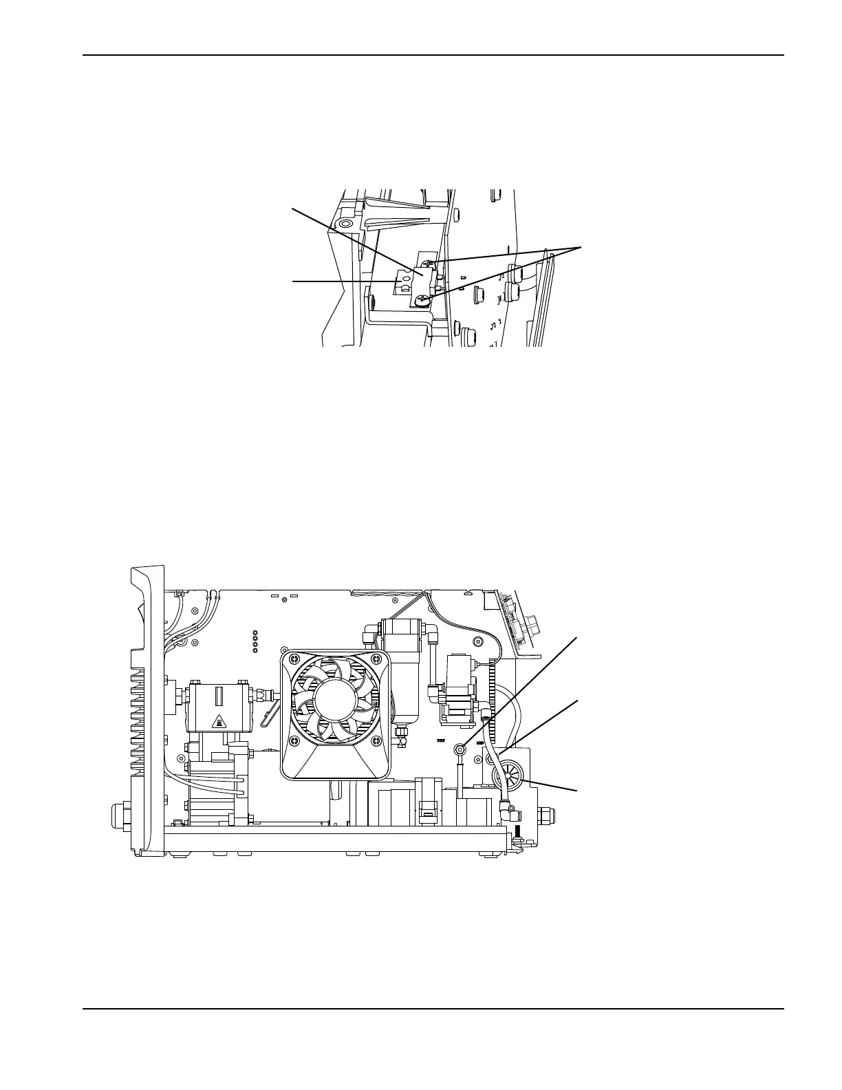
11 . Being careful not to scratch the heatsink, remove the 2 screws from the snubber resistor clip on the top of the
heatsink, and remove the clip.
Figure 50
12. Disconnect the bottom two wires (both are white) from the power switch.
13. Use an 8 mm (5/16-inch) nut driver to remove the nuts that attach the red and the white wires to the studs on the fan
side of the power supply. The studs are labeled “RED” and “WHT.”
14. Pull the red and white wires through the grommet in the center panel of the power supply.
Figure 51
15. From the power board side of the power supply, push the wires that you disconnected down and out of the way.
16. Pull the power board straight out from the power supply.
Screws
Clip
Snubber resistor
White (“WHT”)
Red (“RED”)
Grommet

 Loading...


