130 Powermax30 AIR Service Manual 808850
6 – Power Supply Component Replacement
Install the power board
Before beginning this procedure, make sure you have the correct power board for your system.
The replacement kit number for a CSA power board is 428402.
The replacement kit number for a CE power board is 428403.
1. Being careful not to scratch the heatsink, use a clean, soft cloth with isopropyl alcohol to remove any residual thermal
grease.
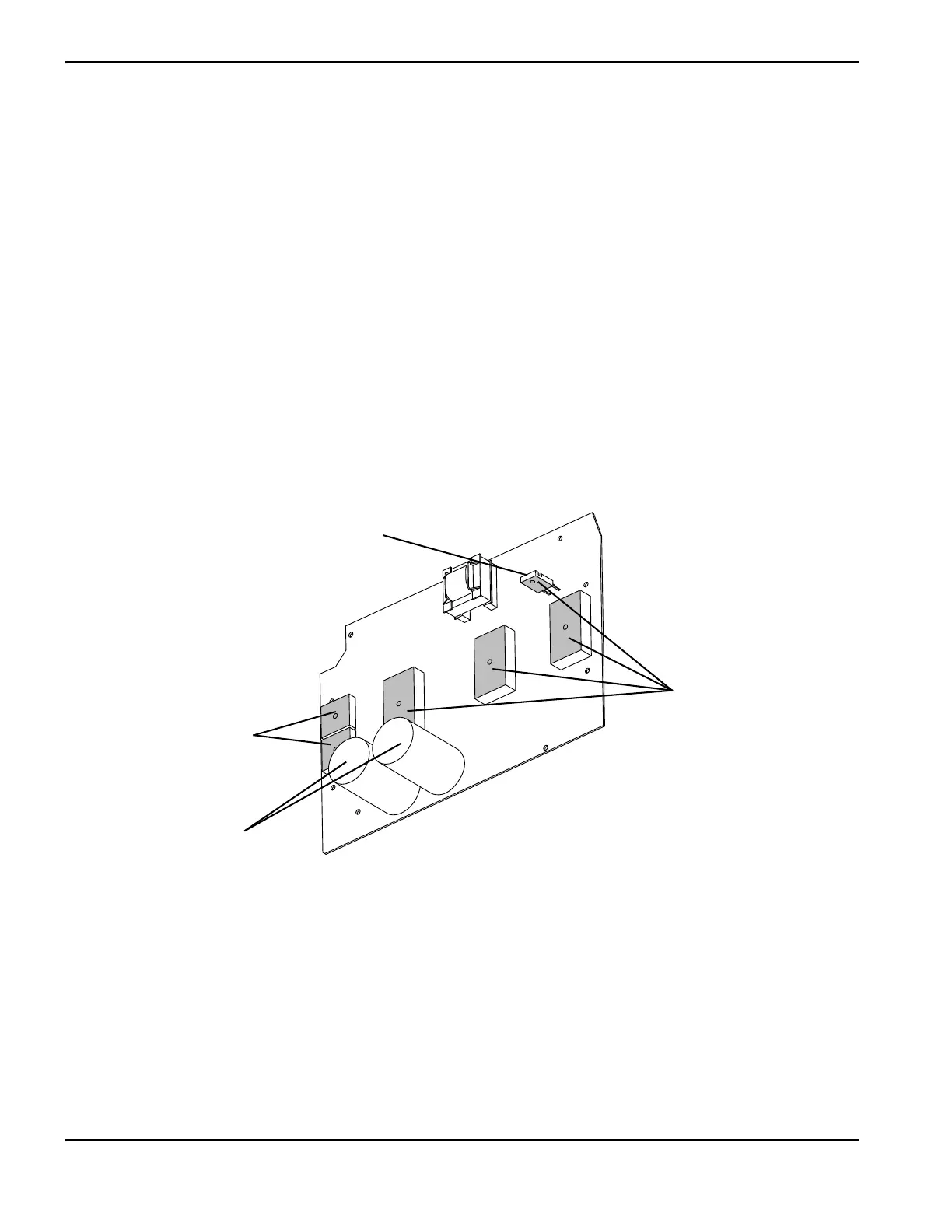
2. Apply a 0.051 mm (0.002 inch) layer of thermal grease, about the thickness of a sheet of paper, on all the IGBTs and
the input diode bridges.
3. Apply thermal grease to the bottom of the snubber resistor as follows.
a. Avoid getting any thermal grease on the prongs of the snubber resistor.
b. Start from the end closest to the power board and drag away from the prongs.
c. Spread an even layer of thermal grease 0.051 mm (0.002 inch) thick on the bottom of the snubber resistor.
Figure 52
Thermal grease applied
Capacitors
Snubber resistor
Thermal grease applied

 Loading...


