Powermax30 AIR Service Manual 808850 131
6 – Power Supply Component Replacement
4. Push the red and white wires on the new power board through the grommet in the center panel from the power
board side of the power supply to the fan side of the power supply.
5. Push the wires that you disconnected down and out of the way.
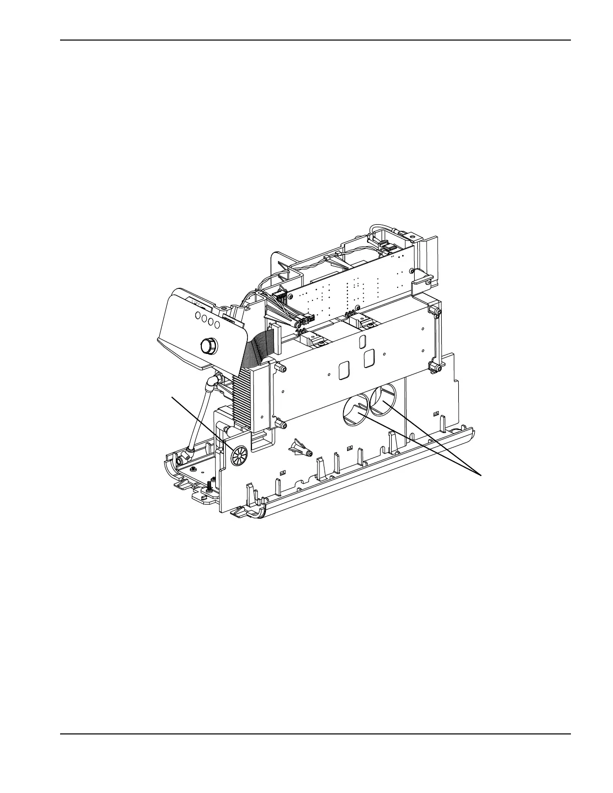
6. Line up the capacitors on the power board with the holes in the power supply’s center panel. See Figure 52 and
Figure 53.
7. Push the power board straight in.
Figure 53
8. Reconnect the 2 white wires to the power switch. Connect the left “AC” wire to the bottom-left pin on the power
switch. Connect the right “AC” wire to the bottom-right pin on the power switch.
9. Replace the 4 heatsink assembly screws. Tighten the screws to 17.3 kg∙cm (15 inch∙pounds).
10. Replace the 3 screws that attach the IGBTs to the heatsink and the 2 screws that attach the input diode bridges to
the heatsink. Tighten the screws to 23.0 kg∙cm (20 inch∙pounds).
11 . Replace the 2 retaining screws. Tighten the screws to 17.3 kg∙cm (15 inch∙pounds).
Grommet for red and white
wires
Holes for capacitors

 Loading...


