EasyManuals Logo

Hypertherm Powermax30 AIR Service Manual

Hypertherm Powermax30 AIR
223 pages
To Next Page IconTo Next Page
To Previous Page IconTo Previous Page
Page #145 background imageLoading...
Page #145 background image
Powermax30 AIR Service Manual 808850 145
6 Power Supply Component Replacement
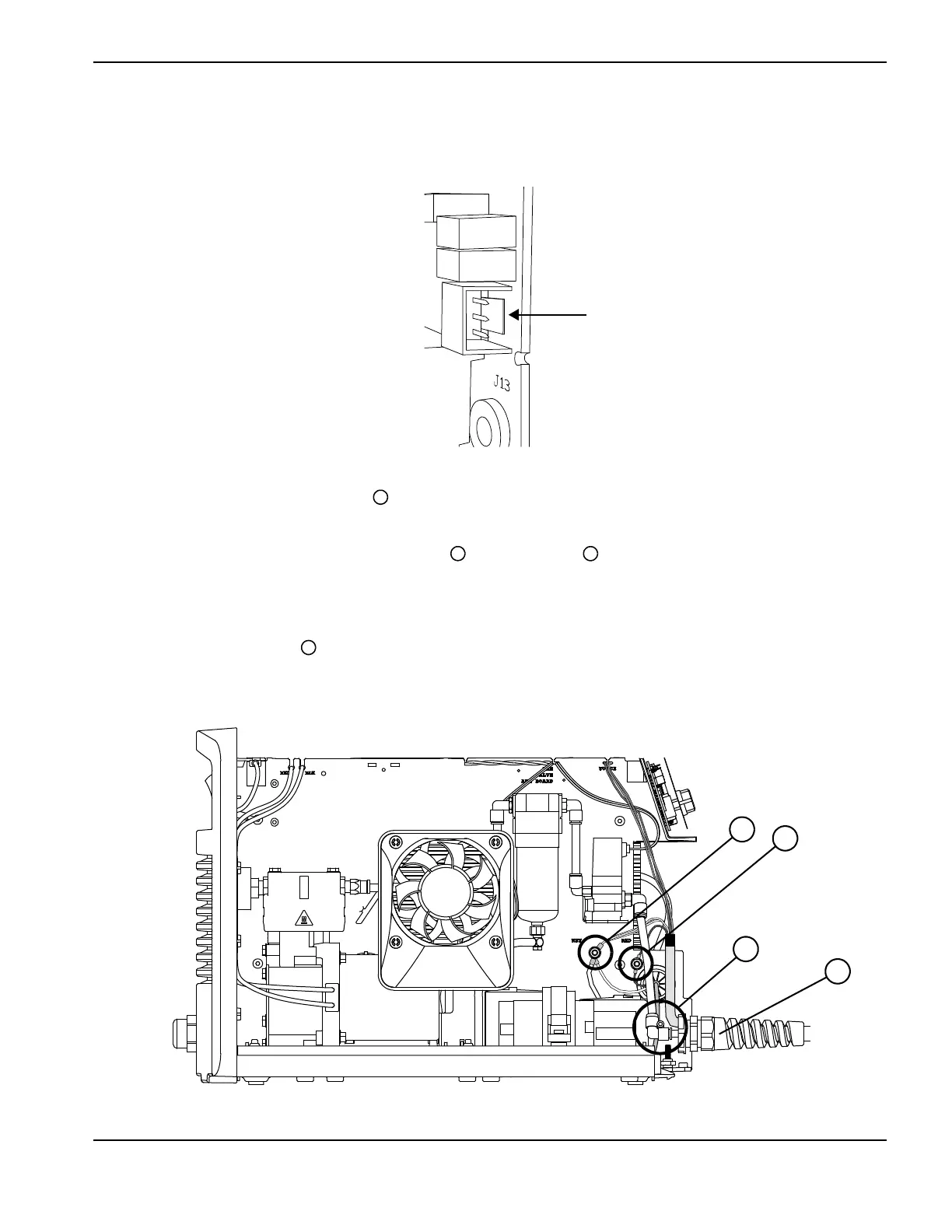
3. Remove the connector at J12 by pushing the tab on the connector toward the plug and pulling the plug out.
Figure 61
4. Push-to-release the plastic 90° fitting from the torch lead’s brass gas supply fitting inside the front panel of the
power supply. (See How to use push-to-connect fittings on page 133.)
5. Locate the studs that attach the white wire group and the red wire from the torch lead to the power supply’s
center panel (on the fan side of the power supply).
6. Use an 8 mm (5/16 inch) nut driver to remove the nuts from the studs, and slide the ring terminals off the studs.
7. Loosen the strain relief nut on the torch lead outside the front panel.
Figure 62
Push tab toward plug
2
3
4
5
2
3
5
4

Table of Contents

Other manuals for Hypertherm Powermax30 AIR

Questions and Answers:

Question and Answer IconNeed help?

Do you have a question about the Hypertherm Powermax30 AIR and is the answer not in the manual?

Hypertherm Powermax30 AIR Specifications

General IconGeneral
Built-in Air CompressorYes
Output Voltage83 VDC
Input Voltage120-240 V
Current Output15–30 A
Cutting ThicknessUp to 10 mm (3/8 in) recommended cut
Gas SupplyBuilt-in air compressor
Operating Temperature-10°C to +40°C (+14°F to +104°F)

Related product manuals