EasyManuals Logo

Hypertherm Powermax30 AIR Service Manual

Hypertherm Powermax30 AIR
223 pages
To Next Page IconTo Next Page
To Previous Page IconTo Previous Page
Page #189 background imageLoading...
Page #189 background image
Powermax30 AIR Service Manual 808850 189
7 Torch Component Replacement
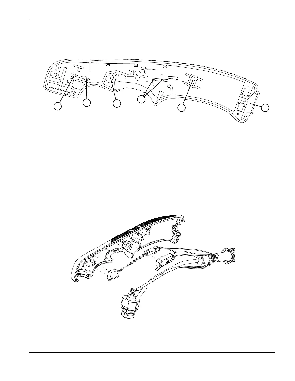
8. Slide the cap-sensor switch off its mounting post. See Figure 96 and Figure 97.
Figure 96
9. Slide the start switch off the 2 mounting posts.
Figure 97
1
2
3
4
5
6
1
Cap-sensor switch’s post hole
2
Cap-sensor switch’s mounting post
3
Trigger’s pivot hole
4
Start switch’s mounting posts
5
Slot for the gas hose fitting’s flange
6
Strain relief slot

Table of Contents

Other manuals for Hypertherm Powermax30 AIR

Questions and Answers:

Question and Answer IconNeed help?

Do you have a question about the Hypertherm Powermax30 AIR and is the answer not in the manual?

Hypertherm Powermax30 AIR Specifications

General IconGeneral
Built-in Air CompressorYes
Output Voltage83 VDC
Input Voltage120-240 V
Current Output15–30 A
Cutting ThicknessUp to 10 mm (3/8 in) recommended cut
Gas SupplyBuilt-in air compressor
Operating Temperature-10°C to +40°C (+14°F to +104°F)

Related product manuals