88 Powermax30 AIR Service Manual 808850
5 – Troubleshooting and System Tests
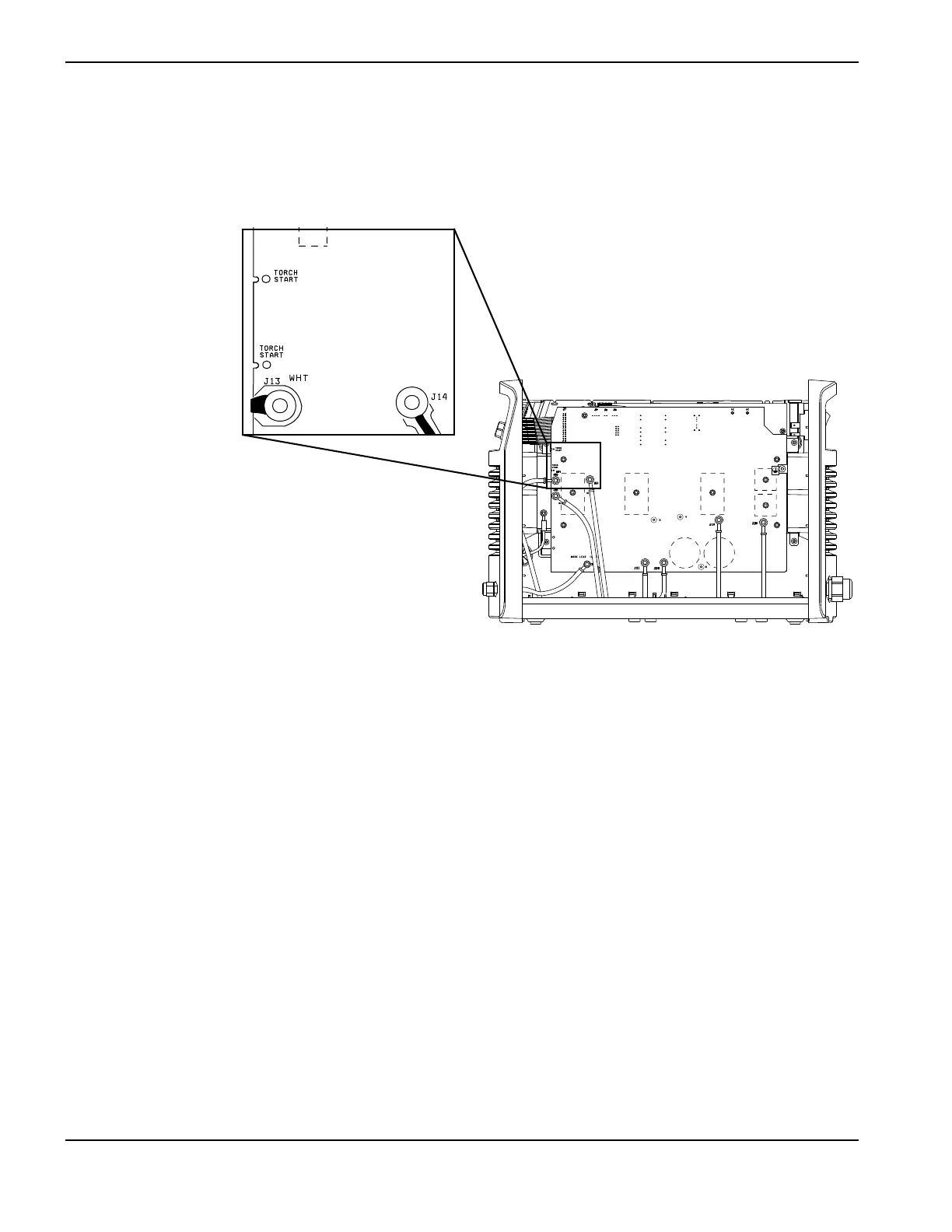
7. Check the resistance at the 2 torch-start test points on the power board. See Figure 16.
a. With the trigger pulled, the resistance should read 10 Ω or less.
b. With the trigger released, the circuit should read approximately 3 kΩ.
Figure 16
8. If this test fails, check the torch start switch and the torch wires. Replace if necessary. See Replace the start switch
on page 195 or Replace the torch lead and strain relief on page 144.
9. Turn ON (I) the power.
10. Measure pin 16 of J7 to ground. See Test 2 – power board voltage checks on page 80.
a. With the trigger pulled, it should measure as 0 VDC for an open circuit.
b. With the trigger released, it should measure 3.2 VDC for a closed circuit.
11 . Are the values correct?
If yes, replace the control board. See Replace the control board on page 118.
If no, replace the power board. See Replace the power board on page 126.
WORK LEAD (BLK)
AC AC
R
w
TORCH
START
BLK
BLK
B
TORCH
START