Home
IEI Technology
Touch Panel
AFL-xxx-CX2
IEI Technology AFL-xxx-CX2 - User Manual
201 pages
Manual
Specs
Ask a question
Save Page as PDF
To Next Page
To Next Page
Loading...
AFL-xxx-CX2 Panel PC
Page i
MODEL:
AFL-xxx-CX2
Panel PC with T
ouch Screen and
V
IA
®
EDEN CPU
Gigabit Ethernet, Four USB,
Audio, RS-232/422/485, SA
T
A
RoHS Compliant, IP
64 Protection
Rev
. 1.00 September
, 2008
User Manual
2
Table of Contents
Main Page
Default Chapter
6
Packing List
6
Table of Contents
7
1 Introduction
19
Overview
20
Applications
21
Model Variations
21
Table 1-1: Model Variations
21
Standard Features
22
Figure 1-2: Front View
23
Figure 1-3: Rear View
24
Rear Panel
24
Figure 1-4: Bottom View
25
Internal Overview
25
Preinstalled Hardware Components
26
Specifications
26
Bottom Panel
24
External Overview
22
General Description
22
Front Panel
23
Figure 1-5: AFL-XXX-CX2 Internal Overview
26
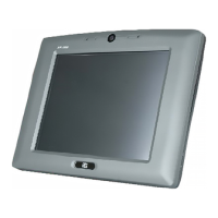
Figure 1-1: AFL-XXX-CX2
27
Table 1-2: System Specifications
28
Afl-07A-Cx2
29
Afl-08Ah-Cx2
29
Flat Panel Screen Specifications
29
Table 1-3: Motherboard Specifications
29
Table 1-4: AFL-07A-CX2 TFT LCD Monitor Specifications
29
Table 1-5: AFL-08AH-CX2 TFT LCD Monitor Specifications
30
Table 1-6: AFL-10A-CX2 TFT LCD Monitor Specifications
30
Afl-12B-Cx2
31
Table 1-7: AFL-12B-CX2 TFT LCD Monitor Specifications
31
Touch Screen Specifications
31
Bluetooth Module Specifications
32
Table 1-8: Touch Panel Specifications
32
Dimensions
33
Optional HSDPA Module Specifications
33
Table 1-10: HSDPA Module Specifications
33
Table 1-9: Bluetooth Module Specifications
33
AFL-07A-CX2 Dimensions
34
Figure 1-6: AFL-07A-CX2 Dimensions (Units in MM)
34
AFL-08AH-CX2 Dimensions
35
Figure 1-7: AFL-08AH-CX2 Dimensions (Units in MM)
35
AFL-10A-CX2 Dimensions
36
Figure 1-8: AFL-10A-CX2 Dimensions (Units in MM)
36
AFL-12B-CX2 Dimensions
37
Afl-10A-Cx2
30
System Specifications
27
Motherboard Specifications
28
Figure 1-9: AFL-12B-CX2 Dimensions (Units in MM)
37
2 Motherboard
38
Cpu Support
39
Introduction
39
System Chipset
39
Gigabit Ethernet
40
Graphics
40
Figure 2-1: Gigabit Ethernet
41
Memory
41
Figure 2-2: Memory Module
42
Figure 2-5: External SATA Hard Drive
44
Figure 2-6: Bluetooth Module
44
Figure 2-7: HSDPA Module
45
Figure 2-8: Wireless LAN Module
46
Wireless Lan
46
Figure 2-9: AFLMB-CX2-R10 Connector Overview
47
Internal Peripheral Device Connectors
47
Touch Screen
47
GPIO Connector
48
Table 2-1: Touch Screen Connector
48
Touch Screen Connector
48
Front Panel Connectors
49
RFID Connector
49
Table 2-2: GPIO Connector
49
Table 2-3: RFID Connector
49
Keypad Connector
50
MCU Program Connector
50
Table 2-4: Front Panel Connectors
50
Table 2-5: MCU Program Connector
50
Backlight Connector
51
CPLD Connector
51
Table 2-6: Keypad Connector
51
Table 2-7: Backlight Connector
51
PS/2 Connector
52
Table 2-8: CPLD Connector
52
Table 2-9: PS/2 Connector
52
VGA Connector
52
Compactflash® Connector
53
Hard Drive Power Connector
53
Table 2-10: VGA Connector
53
Table 2-11: Hard Drive Power Connector
53
Primary IDE Connector
54
Table 2-12: Compactflash® Connector
54
Audio Output Connector
55
Table 2-13: Primary IDE Connector
55
Microphone Input Connector
56
Power Connector
56
Table 2-14: Audio Output Connector
56
Table 2-15: Microphone Input Connector
56
COM1 RS-232 Serial Port Connector
57
COM2 RS-232/422/485 Serial Port Connector
57
Table 2-16: 12 V Power Connector
57
Table 2-17: COM2 Serial Port Connector
57
Digital Microphone Input Connector
58
SATA Ports
58
Table 2-18: COM1 Serial Port Connector
58
Table 2-19: Digital Microphone Input Connector
58
Battery Connector
59
Table 2-20: SATA Connector
59
Table 2-21: Battery Connector
59
CPU Fan Connector
60
LVDS Connector
60
Table 2-22: LVDS Connector
60
Table 2-23: CPU Fan Connector
61
Table 2-24: USB Connectors
61
USB Connectors (Internal)
61
HSDPA Module (Optional)
45
Front Panel
46
LCD Screen
46
Storage
42
Compactflash
42
Figure 2-3: Compactflash® Slot
43
Figure 2-4: Hard Drive Slot
43
Hard Drive
43
Bluetooth Module
44
3 Installation
62
Installation Precautions
63
Preinstalled Components
63
Installation and Configuration Steps
64
Unpacking
64
Packing List
65
Optional Items
66
Table 3-2: Optional Items
66
Table 3-1: Packing List
66
Compactflash Card Installation
67
Figure 3-2: AFL-08AH-CX2 Cover Retention Screws
67
Figure 3-6: AFL-12B-CX2 Cover Retention Screws
69
Figure 3-7: AFL-12B-CX2 Bracket Retention Screws
70
Figure 3-8: AFL-XXX-CX2 Hard Drive Retention Screws
70
Figure 3-9: AT/ATX Switch Location
71
AT Power Mode
72
ATX Power Mode
72
Mounting the System
72
Figure 3-10: Wall-Mounting Bracket
73
Wall Mounting
73
Figure 3-11: Chassis Support Screws
74
Arm Mounting
75
Figure 3-12: Secure the Panel PC
75
Figure 3-13: Arm Mounting Screw Holes (AFL-07A-CX2 and AFL-08AH-CX2)
76
Figure 3-14: Arm Mounting Screw Holes (AFL-10A-CX2 and AFL-12B-CX2)
77
Panel Mounting
77
Figure 3-3: AFL-10A-CX2 Cover Retention Screws
67
At/Atx Mode Selection
71
Figure 3-15: AFL-07A-CX2 Panel Opening
78
Figure 3-16: AFL-08AH-CX2 Panel Opening
78
Figure 3-19: Tighten the Panel Mounting Clamp Screws
80
Figure 3-20: the Rack/Cabinet Bracket
81
Figure 3-21: Secure the Rack/Cabinet Bracket
82
Figure 3-22: Install into a Rack/Cabinet
82
Bottom Panel Connectors
83
Figure 3-23: LAN Connection
83
LAN Connection
83
Figure 3-24: Serial Device Connector
84
Serial Device Connection
84
USB Device Connection
85
Figure 3-18: AFL-12B-CX2 Panel Opening
79
Figure 3-17: AFL-10A-CX2 Panel Opening
79
Cabinet and Rack Installation
80
Figure 3-1: AFL-07A-CX2 Cover Retention Screws
67
Figure 3-4: AFL-12B-CX2 Back Cover Retention Screws
68
Figure 3-5: Compactflash® Card Slot Location
68
Hard Drive Installation
68
Figure 3-25: USB Device Connection
85
4 System Maintenance
86
Internal Aluminum Cover Removal
87
Motherboard Replacement
87
System Maintenance Introduction
87
Figure 4-1: AFL-07A-CX2 Aluminum Back Cover Retention Screws
88
Figure 4-2: AFL-08AH-CX2 Aluminum Back Cover Retention Screws
89
Figure 4-3: AFL-10A-CX2 Aluminum Back Cover Retention Screws
89
Figure 4-4: AFL-12B-CX2 Aluminum Back Cover Retention Screws
90
Figure 4-5: Memory Module
91
Figure 4-6: DDR2 SO-DIMM Module Installation
92
Jumper Settings
92
Figure 4-7: Jumper Locations
93
AT/ATX Power Selection (JP18)
94
Clear CMOS (JP5)
94
Compactflash Master/Slave Selection (JP8)
94
Table 4-1: AT/ATX Power Selection
94
Table 4-2: Clear CMOS
94
Table 4-4: COM1 Pin-9 Setting
95
Table 4-5: COM2 Pin-9 Setting
95
Table 4-6: COM2 Mode Select
95
COM2 RS-422/485 Select (JP15)
96
LCD Voltage Selection (JP4)
96
Pin-12 Signal Setting (JP8)
96
Table 4-7: COM2 Mode Select
96
Table 4-8: COM2 Mode Select Jumper Settings
96
Panel Resolution (JP2)
97
Table 4-9: LCD Voltage Setup Jumper Settings
97
Touch Panel Type (J1)
97
Table 4-3: Compactflash® Master/Slave Selection
94
COM1 Pin-9 Setting (JP6)
95
COM2 Settings
95
COM2 Mode Select (JP7)
95
COM2 Pin-9 Setting (JP6)
95
Memory Module Replacement
90
Table 4-10: COM2 Mode Select Jumper Settings
97
Table 4-11: Touch Panel Type
97
5 Bios Setup
98
Introduction
99
Starting Setup
99
Using Setup
99
Getting Help
100
Unable to Reboot after Configuration Changes
100
BIOS Menu Bar
100
Table 5-1: BIOS Navigation Keys
100
BIOS Menu 1: Main
101
Advanced
102
Main
101
BIOS Menu 2: Advanced
103
CPU Configuration
104
BIOS Menu 3: CPU Configuration
104
IDE Configuration
105
BIOS Menu 4: IDE Configuration
105
IDE Master, IDE Slave
106
BIOS Menu 5: IDE Master and IDE Slave Configuration
106
Super IO Configuration
111
BIOS Menu 6: Super IO Configuration
111
Remote Access Configuration
113
BIOS Menu 7: Remote Access Configuration [Advanced]
113
USB Configuration
116
BIOS Menu 8: USB Configuration
116
USB Mass Storage Device Configuration
118
BIOS Menu 9: USB Mass Storage Device Configuration
118
Power Configuration
120
BIOS Menu 10: Power Configuration
120
ACPI Configuration
121
BIOS Menu 11: ACPI Configuration
121
APM Configuration
122
BIOS Menu 12:Advanced Power Management Configuration
122
Pci/Pnp
124
BIOS Menu 13: Pci/Pnp Configuration
124
Boot
126
BIOS Menu 14: Boot
126
Boot Settings Configuration
127
BIOS Menu 15: Boot Settings Configuration
127
Boot Device Priority
129
BIOS Menu 16: Boot Device Priority Settings
129
Hard Disk Drives
130
BIOS Menu 17: Hard Disk Drives
130
Removable Drives
131
BIOS Menu 18: Removable Drives
131
Security
132
BIOS Menu 19: Security
132
Chipset
133
BIOS Menu 20: Chipset
133
Northbridge Configuration
134
BIOS Menu 21:Northbridge Chipset Configuration
134
Southbridge Configuration
136
BIOS Menu 22:Southbridge Chipset Configuration
136
Exit
137
BIOS Menu 23:Exit
137
6 Driver Installation
139
Available Software Drivers
140
Driver CD Auto-Run
140
Chipset Driver
141
Figure 6-1: Available Drivers
141
Figure 6-2: Chipset Driver Icon
142
Figure 6-4: Chipset Driver License Agreement
143
Figure 6-5: Chipset Driver List
143
Figure 6-8: Chipset Driver Installed Drivers
145
Figure 6-9: Graphics Driver Installation
146
Figure 6-10: VGA Driver
147
Figure 6-11: Windows Control Panel
148
Gigabit Ethernet Driver
148
Figure 6-12: System Icon
149
Figure 6-13: System Properties
149
Figure 6-14: Ethernet Controller
150
Figure 6-15: Hardware Update Wizard
150
Figure 6-18: Select the Audio CODEC
152
Figure 6-19: Audio Driver Installation
153
Figure 6-20: Audio Driver Installation Windows
153
Figure 6-21: Installshield Wizard Welcome Screen
154
Touch Panel Driver
154
Figure 6-22: S-Video Patch Folder
155
Figure 6-23: Access Startup Folder
155
Figure 6-24: Start Touch Panel Driver Installation
156
Figure 6-25: Windows Logo Testing
156
Figure 6-26: Create Shortcut Wizard
157
Wireless Lan Mini Pci Card Driver
157
Figure 6-27: Software Driver Folder
158
Figure 6-28: 802.11G Wireless Mini PCI Card Welcome Screen
158
Figure 6-29: Configuration Tool Selection
159
Figure 6-30: Optimization Mode
159
Figure 6-31: Wireless Mini PCI Card Driver Installation Screen
160
Figure 6-32: Installshield Wizard Complete Screen
160
Bluetooth Driver
161
Figure 6-17: LAN Driver Installation Complete
151
Figure 6-16: Search for LAN Driver
151
Audio Driver
152
BIOS Setup
152
Driver Installation
152
Figure 6-3: Chipset Driver Welcome Screen
142
Figure 6-6: Chipset Driver List
144
Figure 6-7: Chipset Driver Installed Drivers
144
Graphics Driver
145
Figure 6-33: USB2.0 Window
161
Figure 6-34: Language Selection
161
Figure 6-35: Bluetooth Installshield Wizard
162
Figure 6-36: Bluesoleil License Agreement
162
Figure 6-37: Bluesoleil Custom Settings
163
Figure 6-38: USB 2.0 Installshield Wizard Welcome Screen
164
Figure 6-39: Ready to Install Bluetooth
165
Figure 6-40: USB 2.0 Driver Installed
166
ABIOS Options
167
B Terminology
170
C Digital I/O Interface
174
Introduction
175
Dio Connector Pinouts
175
C.1 I Ntroduction
175
Assembly Language Samples
176
Enable the DIO Input Function
176
Enable the DIO Output Function
176
D Watchdog Timer
177
E Address Mapping
180
Direct Memory Access (Dma)
181
E.1 D Irect M Emory a Ccess (Dma)
181
Input/Output (IO)
182
E.2 I Nput /O Utput (Io)
182
Interrupt Request (Irq)
184
E.3 I Nterrupt R Equest (Irq)
184
Memory
185
F Compatibility
186
Compatible Operating Systems
187
Compatible Processors
187
Compatible Memory Modules
188
G Hazardous Materials Disclosure
189
Hazardous Materials Disclosure Table for IPB Products Certified as Rohs Compliant under 2002/95/EC Without Mercury
190
H Ac'97 Audio Codec
193
Introduction
194
Accessing the AC'97 CODEC
194
Driver Installation
194
H.1 I Ntroduction
194
Sound Effect Configuration
195
Accessing the Sound Effects Manager
195
Sound Effect Manager Configuration Options
196
Need help?
Do you have a question about the IEI Technology AFL-xxx-CX2 and is the answer not in the manual?
Ask a question
IEI Technology AFL-xxx-CX2 Specifications
Print Specification
General
Touch Technology
Projected Capacitive
System Memory
4GB DDR3L
Operating System
Windows 10 IoT
IP Rating
IP65
Ports
1 x HDMI
Power Supply
9V to 36V DC
Related product manuals
IEI Technology AFL-xxx-9103
203 pages
IEI Technology AFL-08B-N270
132 pages
IEI Technology AFL-HM55 Series
139 pages
IEI Technology ICEFIRE2-T10
154 pages
IEI Technology POC-W24C-ULT3
160 pages