AFL-xxx-CX2 Panel PC
Page 35
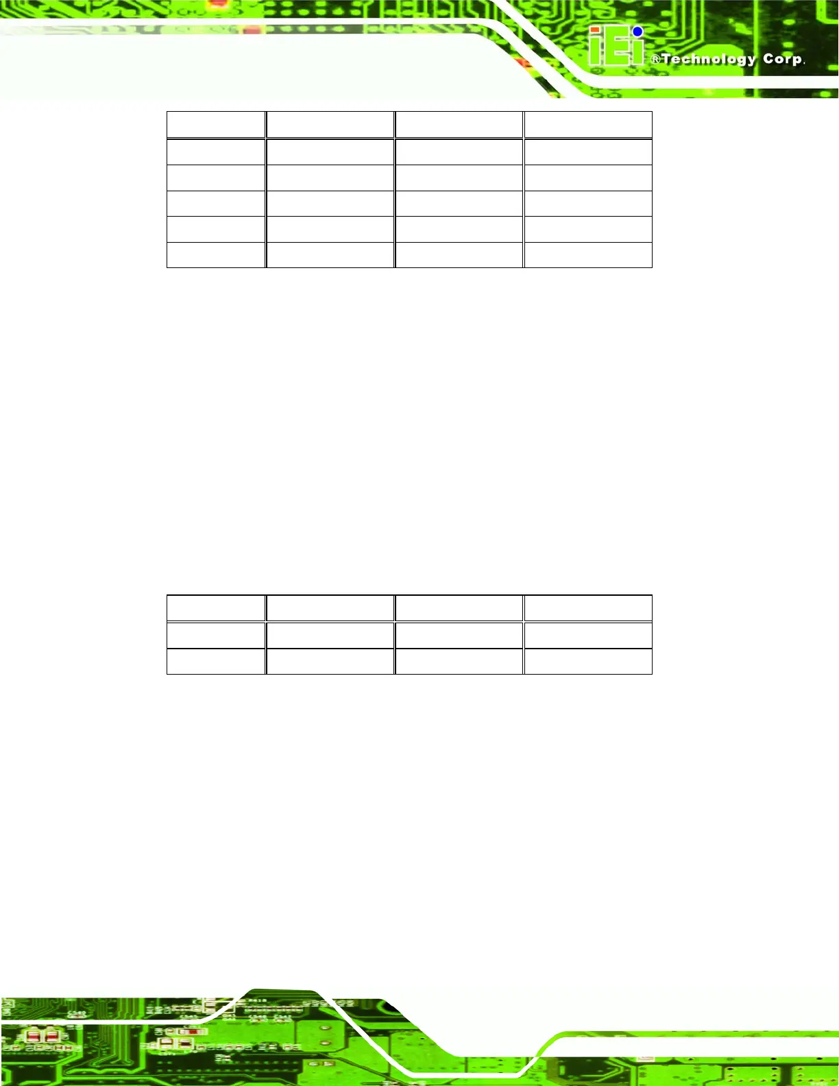
PIN DESCRIPTION PIN DESCRIPTION
1 RED 2 DDCDAT
3 GREEN 4 DDCCLK
5 BLUE 6 GND
7 VSYNC 8 GND
9 HSYNC 10 GND
Table 2-10: VGA Connector
2.12.11 Hard Drive Power Connector
CN Label: CN9
CN Type:
4-pin box header
CN Location:
See
Figure 2-9
CN Pinouts:
See
Table 2-11
The hard drive power connector provides power to an hard drive installed in the
AFL-xxx-CX2. The hard drive power connector is specifically intended to be used with an
installed SATA hard drive.
PIN DESCRIPTION PIN DESCRIPTION
1 +5 V 2 GND
3 GND 4 +12 V
Table 2-11: Hard Drive Power Connector
2.12.12 CompactFlash® Connector
CN Label: CN10
CN Type:
CompactFlash® connector
CN Location:
See
Figure 2-9
CN Pinouts:
See
Table 2-12
The CompactFlash® slot allows a Type I/II CompactFlash® card to be installed in the
AFL-xxx-CX2.
 Loading...