AFL-xxx-CX2 Panel PC
Page 32
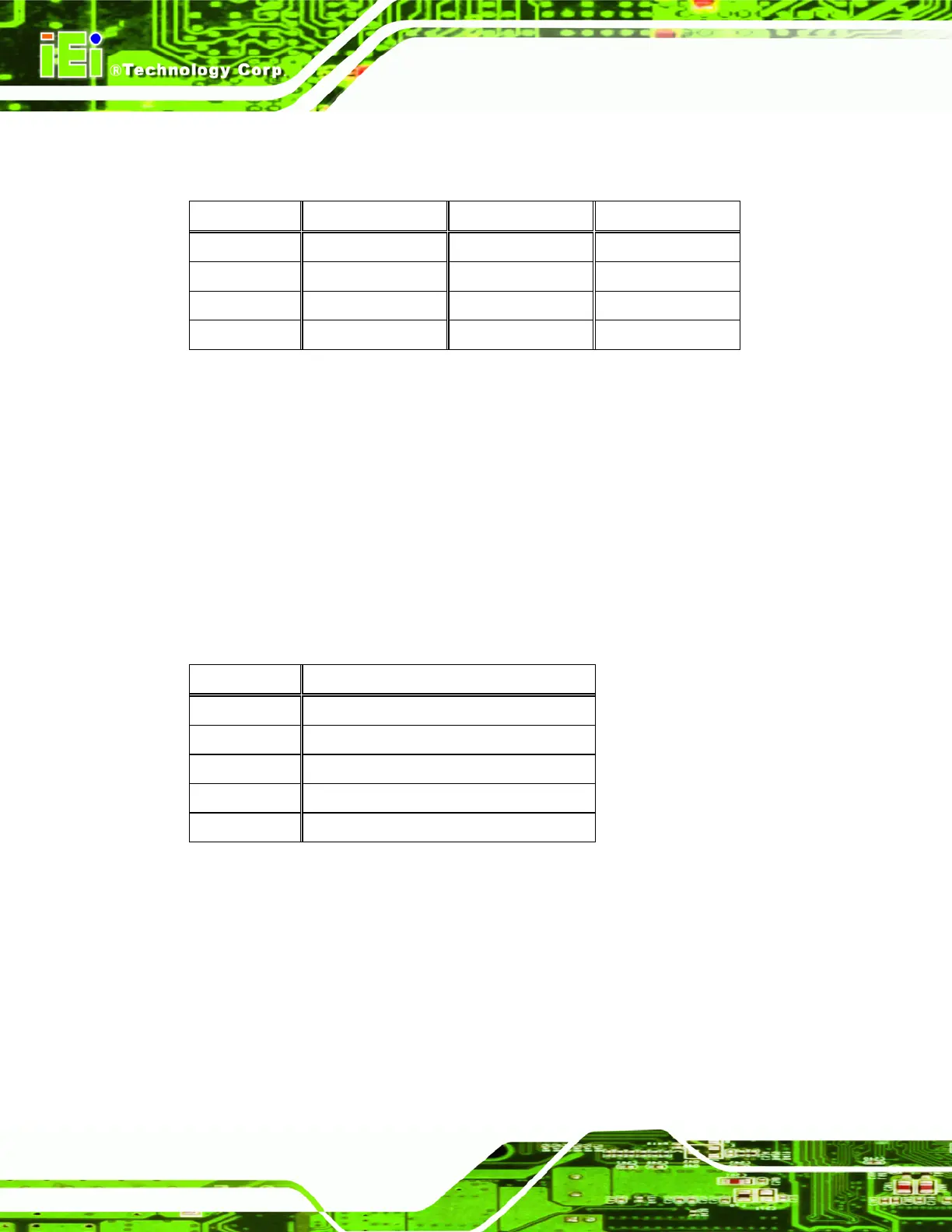
The front panel connectors connect to the buttons and indicators on the front panel. These
include the power and reset buttons, and the hard drive and power LEDs.
PIN DESCRIPTION PIN DESCRIPTION
1 Power LED + 2 HDDLED+
3 Power LED - 4 HDDLED-
5 RESET_SW+ 6 PWRBT_SW+
7 RESET_SW- 8 PWRBT_SW-
Table 2-4: Front Panel Connectors
2.12.5 MCU Program Connector
CN Label: JP16
CN Type:
12-pin connector (5 pins for MCU program connector)
CN Location:
See
Figure 2-9
CN Pinouts:
See
Table 2-5
The MCU program connector is for MCU program control.
PIN DESCRIPTION
1 MCLR
3 +5 V
5 GND
7 ICSPCLK
9 ICSPDAT
Table 2-5: MCU Program Connector
2.12.6 Keypad Connector
CN Label: JP16
CN Type:
12-pin connector (6 pins for keypad connector)
CN Location:
See
Figure 2-9
CN Pinouts:
See
Table 2-6
 Loading...