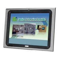
AFL-xxx-CX2 Panel PC
Page 38
CN Type:
4-pin connector
CN Location:
See
Figure 2-9
CN Pinouts:
See
Table 2-14
The audio output connector connects to speakers.
PIN DESCRIPTION PIN DESCRIPTION
1 OUTL 2 GND
3 GND 4 OUTR
Table 2-14: Audio Output Connector
2.12.15 Microphone Input Connector
CN Label: CN13
CN Type:
4-pin connector
CN Location:
See
Figure 2-9
CN Pinouts:
See
Table 2-15
The microphone input connector connects to a microphone for audio input.
PIN DESCRIPTION PIN DESCRIPTION
1 INL 2 GND
3 GND 4 INR
Table 2-15: Microphone Input Connector
2.12.16 12 V Power Connector
CN Label: CN14
CN Type:
3-pin box header
CN Location:
See
Figure 2-9
CN Pinouts:
See
Table 2-16
The 12 V power connector provides 12 V of power to connected devices.
 Loading...