AFL-xxx-CX2 Panel PC
Page 58
Step 1: The arm is a separately purchased item. Please correctly mount the arm onto
the surface it uses as a base. To do this, refer to the installation documentation
that came with the mounting arm.
NOTE:
When purchasing the arm please ensure that it is VESA compliant and
that the arm has the correct interface pad. If the mounting arm is not
VESA compliant it cannot be used to support the AFL-xxx-CX2.
Step 2: Once the mounting arm has been firmly attached to the surface, lift the flat panel
PC onto the interface pad of the mounting arm.
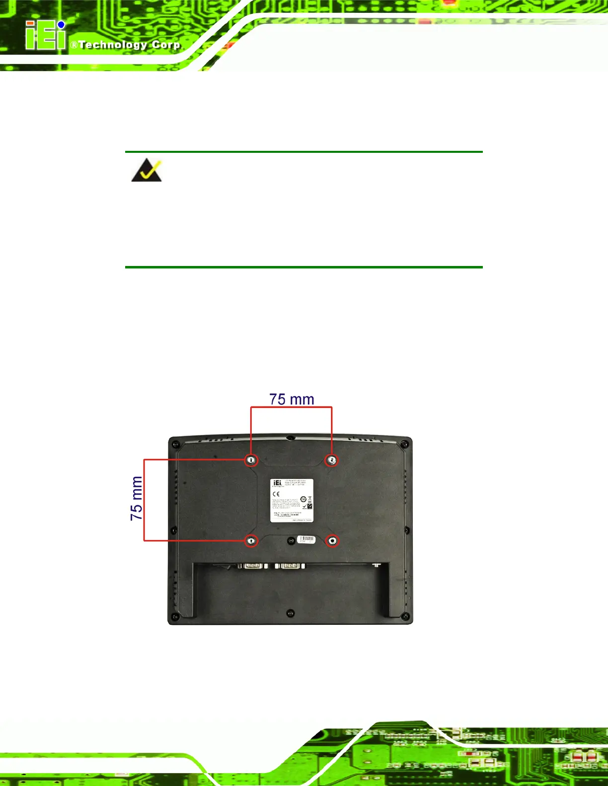
Step 3: Align the retention screw holes on the mounting arm interface with those in the
flat panel PC. The AFL-xxx-CX2 arm mount retention screw holes are shown in
Figure 3-13 and Figure 3-14.
Figure 3-13: Arm Mounting Screw Holes (AFL-07A-CX2 and AFL-08AH-CX2)
 Loading...