HD2 Series Inverter Basic Operation Guidelines
-95-
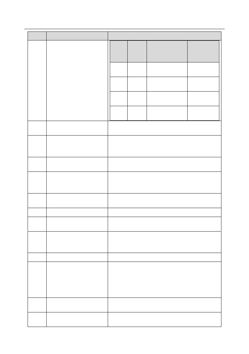
Acceleration/deceleration time
selection 2
Acceleration or
deceleration time
selection
Acceleration/
deceleration time 1
Acceleration/
deceleration time 2
Acceleration/
deceleration time 3
Acceleration/
deceleration time 4
Restart simple PLC process and clear previous PLC
state information.
The program pauses during PLC execution and keeps
running in current speed step. After this function is
cancelled, simple PLC keeps running.
PID is ineffective temporarily, and the inverter maintains
current frequency output.
Wobbling frequency pause
(stop at current frequency)
The inverter pauses at current output. After this function
is canceled, it continues wobbling-frequency operation at
current frequency.
Wobbling frequency reset
(revert to center frequency)
The set frequency of inverter reverts to center frequency.
Zero out the counter state.
Switching between speed
control and torque control
The inverter switches from torque control mode to speed
control mode, or vice versa.
Acceleration/deceleration
disabled
Ensure the inverter will not be impacted by external
signals (except for stop command) and maintains current
output frequency.
Enable pulse counting of the counter.
Clear frequency
increase/decrease setting
temporarily
When the terminal is closed, the frequency value set by
UP/DOWN can be cleared to restore to the frequency
given by frequency command channel; when the terminal
is disconnected, it will revert to the frequency value after
frequency increase/decrease setting.
The inverter starts DC brake immediately after the
command becomes valid.
Switching between motor 1
and motor 2
When this terminal is valid, you can realize switchover
control of two motors.