HD2 Series Inverter Function Parameter List
-141-
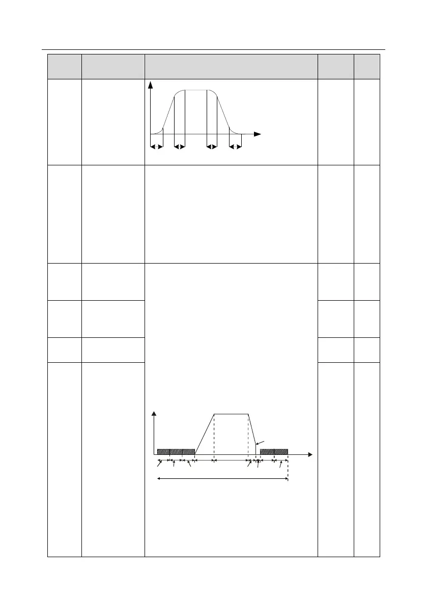
Time of ending
section of
acceleration S
curve
Output frequency f
Time t
t1 t2 t3 t4
t1=P01.06
t2=P01.07
t3=P01.27
t4=P01.28
0: Decelerate to stop; after stop command is valid,
the inverter lowers output frequency based on the
deceleration mode and the defined deceleration
time, after the frequency drops to the stop speed
(P01.15), the inverter stops.
1: Coast to stop; after stop command is valid, the
inverter stops output immediately, and the load
coasts to stop as per mechanical inertia.
Starting
frequency of DC
brake after stop
Starting frequency of DC brake after stop; during
decelerating to stop, when this frequency is
reached, DC brake will be performed after stop.
Demagnetization time (waiting time of DC brake
after stop): Before the DC brake, the inverter will
block output, and after the demagnetization time
elapses, DC brake will start. This function is used
to prevent overcurrent fault caused by DC brake
during high speed.
DC brake current after stop: it means the DC brake
force applied, the larger the current, the stronger
the DC brake effect.
P01.04
Acceleration
P13.14
P01.23
Constant speed
In running
Deceleration
P01.10
P13.15
P01.12
P01.09
Time t
Setting range of P01.09: 0.00Hz–P00.03 (Max.
output frequency)
Setting range of P01.10: 0.00–30.00s
Setting range of P01.11: 0.0–100.0% (of the rated
inverter output current)
Setting range of P01.12: 0.0–50.0s
Waiting time of
DC brake after
stop