HD2 Series Inverter Communication
-307-
1# 2 # 3 # 4 # 32 #
120Ω
120Ω
Figure 9-2 On-site chrysanthemum connection diagram
1# 2# 3# 31#Master
A+
B-
A+ B-
Figure 9-3 Simplified chrysanthemum connection diagram
IMO
VFD
Address 1
Earth
485+
485-
485+
485-
485+
485-
120Ω
Terminal resistor
PC
Converter
GND
RS232-RS485
Max. length of the
cable: 15 m
Shielded twisted pair
Address 2 Address N
IMO
VFD
IMO
VFD
Earth Earth
Figure 9-4 Practical application diagram of chrysanthemum connection
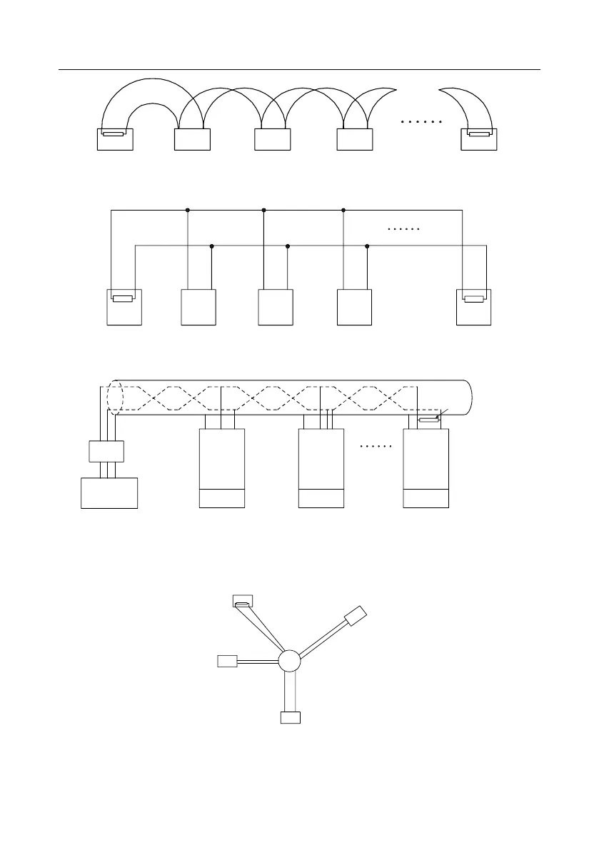
Figure 9-5 shows the start connection diagram. When this connection mode is adopted, the two
devices that are farthest away from each other on the line must be connected with a terminal resistor
(in Figure 9-5, the two devices are devices 1# and 15#).
1#
15#
32#
6
#
Main control
device
Figure 9-5 Star connection
Use shielded cable, if possible, in multi-device connection. The baud rates, data bit check settings,
and other basic parameters of all the devices on the RS485 line must be set consistently, and