HD2 Series Inverter Expansion Cards
-347-
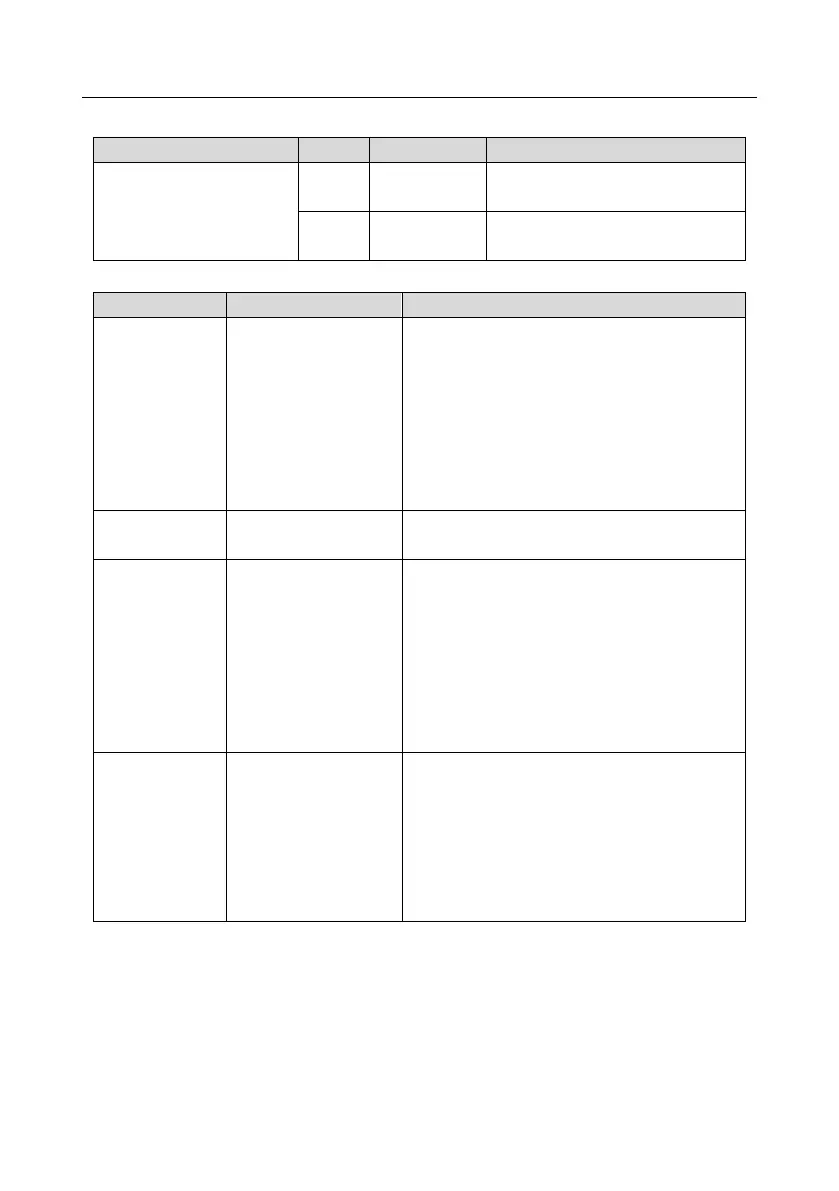
Terminal resistor switch function description
CAN_H and CAN_L are not
connected to a terminal resistor.
CAN_H and CAN_L are connected to
a terminal resistor of 120 Ω.
On: The expansion card is establishing a
connection with the control board.
Blinking periodically: The expansion card is
properly connected to the control board (the
period is 1s, on for 0.5s, and off for the other
0.5s).
Off: The expansion card is disconnected from
the control board.
On: The control board feeds power to the
communication card.
On: The communication card is running.
Off: A fault occurs. Check whether the reset pin
of the communication card and the power supply
are properly connected.
Blinks: The communication card is in the
pre-operation state.
Blinks once: The communication card is in the
stopped state.
On: The CAN controller bus is off, or a fault
occurs on the inverter.
Off: The communication card is in the working
state.
Blinks: The address setting is incorrect.
Blinks once: A received frame is missed or an
error occurs during frame receiving.
For details about the operation, see the HD2 Series inverter Communication Expansion Card
Operation Manual.