HD2 Series Inverter Expansion Cards
-351-
Failed to set up I/O between the card and PLC.
Incorrect PLC configuration.
The card failed to send data to the PLC.
The connection between the card and PLC timed
out.
Link indicator, indicating successful Ethernet
connection.
Link indicator, indicating Ethernet connection not
established.
ACK indicator, indicating data interchange being
performed.
ACK indicator, indicating data interchange is not
performed.
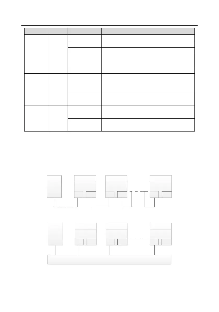
Electrical wiring
The EtherNet/IP communication card provides standard RJ45 ports and supports the linear, star, and
ring topologies. The following three figures show the electrical wiring diagrams.
Use CAT5, CAT5e, and CAT6 network cables for electrical wiring. When the communication distance
is greater than 50 meters, use high-quality network cables that meet the high-quality standards.
Master
(PLC)
Slave 1
CN2 CN1
Slave 2
CN2 CN1
Slave n
CN2 CN1
Figure A-8 Electrical wiring diagram for a linear topology
Master
(PLC)
Slave 1
CN2 CN1
Slave 2
CN2 CN1
Slave n
CN2 CN1
Switch
Figure A-9 Electrical wiring diagram for a star topology
Note: Ethernet switches must be available when the star topology is used.