HD2 Series Inverter Expansion Cards
-352-
Master
(PLC)
Slave 1
CN2 CN1
Slave 2
CN2 CN1
Slave n
CN2 CN1
Figure A-10 Electrical wiring diagram for a ring network
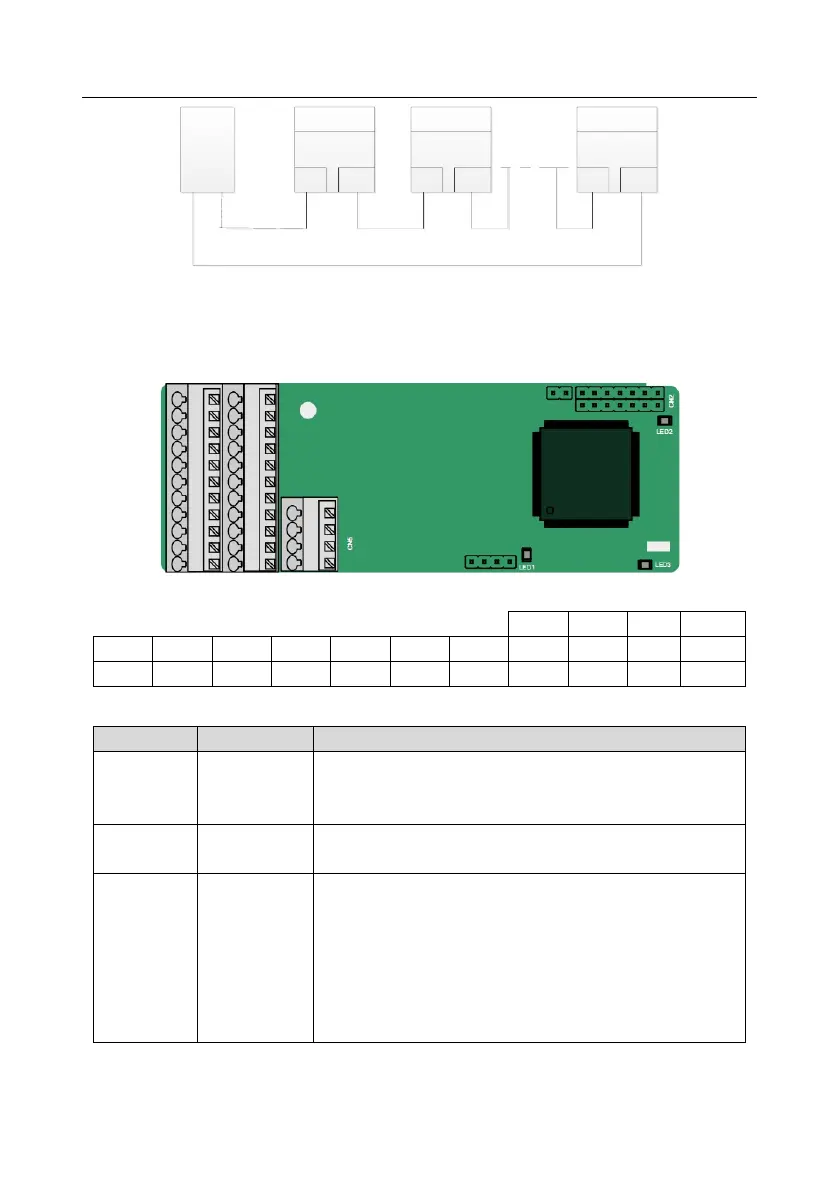
A.8 PG expansion card function description
A.8.1 Sin/Cos PG card (HD2-E-PGISC)
The terminals are arranged as follows:
Off: A1 and B1 of the encoder are disconnected.
Blinking: C1 and D1 of the encoder are disconnected.
On: The encoder signals are normal.
On: The control board feeds power to the PG card.
On: The expansion card is establishing a connection with the
control board.
Blinking periodically: The expansion card is properly
connected to the control board (the period is 1s, on for 0.5s,
and off for the other 0.5s).
Off: The expansion card is disconnected from the control
board.
HD2-E-PGISC terminal function description