HD2 Series Inverter Expansion Cards
-355-
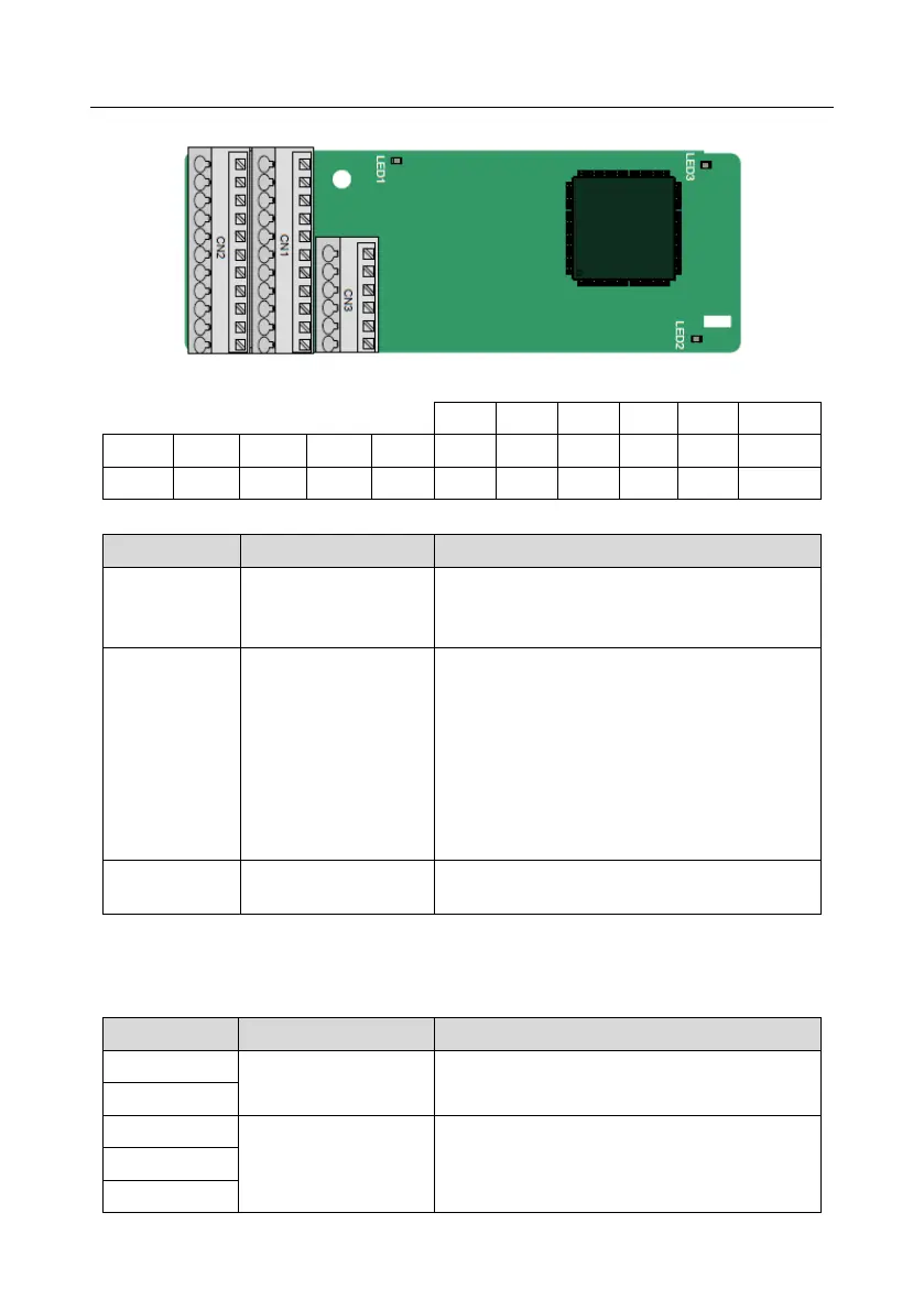
A.8.2 UVW incremental PG card (HD2-E-PGI)
The terminals are arranged as follows:
This indicator blinks only if A1 or B1 signal is
disconnected during encoder rotating; and it is on
in other cases.
On: The expansion card is establishing a
connection with the control board.
Blinking periodically: The expansion card is
properly connected to the control board (the
period is 1s, on for 0.5s, and off for the other
0.5s).
Off: The expansion card is disconnected from the
control board.
On: The control board feeds power to the PG
card.
The HD2-E-PGI expansion card supports the input of absolute position signals and integrates the
advantages of absolute and incremental encoders. It is user-friendly, adopting spring terminals.
HD2-E-PGI terminal function description
Voltage: 5 V±5%
Max. current: 200 mA
1. Differential incremental PG interface of 5 V
2. Response frequency: 400 kHz